Voltage regulator plays a very important role in electronics circuit, because many devices need stable DC voltage.
But sometimes input voltage is only little higher than output voltage, so in this case normal regulator does not work properly.
Therefore, we have used a LDO regulator, LDO means Low Dropout Regulator and it can regulate voltage even when input and output difference is very small.
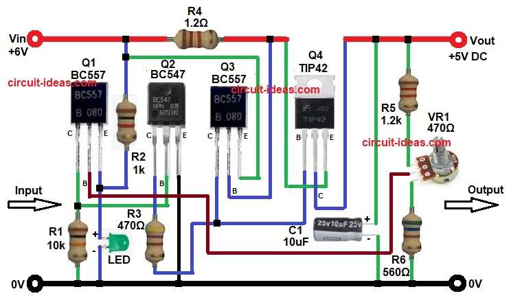
Here, this 5V Transistor Based Low Dropout (LDO) Voltage Regulator Circuit uses transistors instead of IC regulator, so the circuit is simple and is with low cost and also it give around 5V output from 6V input.
Circuit Working:
Parts List:
| Components | Values | Quantity |
|---|---|---|
| Resistors | 1k, 10k, 470Ω, 1.2k, 560Ω, 1.2Ω | 1 each |
| Potentiometer 470Ω | 1 | |
| Capacitor | Electrolytic 10uF 25V | 1 |
| Transistor NPN BC547 | 1 | |
| Transistor PNP BC557 | 2 | |
| Power Transistor PNP TIP42 | 1 | |
| LED Green 5mm 20mA LED | 1 | |
| Heatsink TIP42 | 1 |
The circuit starts with input voltage 6V is applied at Vin.
Then TIP42 Q4 transistor act as main regulator and it connect in series with load, so it control output voltage.
R3 and Q2 form control path for feedback current and VR1 adjusts reference level indirectly.
If output voltage increases then Q3 conduct more, because base-emitter voltage changes.
When Q3 conduct more then it reduces base current of TIP42 Q4, so TIP42 conduct less and as a result output voltage reduces.
On the other hand, if output voltage drop then Q3 conduct less and then TIP42 get more base current, so it conducts more and therefore, output voltage increases again.
In this way feedback system maintain stable 5V output.
Next, Q1 and Q2 provide biasing and current control and they also improve stability.
LED show power ON condition and when input supply is present then LED glows.
C1 capacitor filter noise and improve transient response, so output voltage remain stable during load change.
Therefore, overall circuit work as linear LDO regulator.
How to Build:
To build a 5V Transistor Based Low Dropout (LDO) Voltage Regulator Circuit follow the below connection steps:
- Start, to gather all the components as shown in above circuit diagram.
- Then start with Q1 BC557 emitter pin connect to Vin supply through resistor R2.
- Base connect to middle pin of VR1
- Collector connect to base of Q2 and one end of resistor R1 and other end of R1 goes to GND.
- Then start with Q2 BC547 emitter pin connect to GND of the circuit.
- Collector connect to collector of transistor Q3 and base of transistor Q4 through resistor R3.
- Base pin connect between collector of transistor Q1 and resistor R2.
- Then start with Q3 BC557 emitter connect between Vin and resistor R2 one end.
- Base connect between emitter pin of transistor Q4 and resistor resistor R4 one end.
- Collector pin connect between base of transistor Q4 and resistor R3 one end.
- Then start with last transistor Q4 TIP42 emitter connect to Vin 6V input through resistor R4.
- Collector connect to Vout.
- Base connect to collector of transistor Q3 and one end of resistor R3.
- LED anode connect between emitter of Q1 and resistor R2 one end.
- LED cathode connect to ground.
- Capacitor C1 positive end connect to Vout and negative end connect to ground.
- Lastly, VR1 upper pin connect to resistor R5 middle pin connect to base of Q1 and lower pin connect to GND through resistor R6.
Conclusion:
To conclude, this 5V Transistor Based Low Dropout (LDO) Voltage Regulator Circuit is simple, useful and is with easy design.
It give around 5V output from 6V input supply and therefore, it is good when voltage difference is small.
Moreover, circuit uses common transistors like BC547, BC557 and TIP42, so components are easily available.
However, it is linear regulator, so heat dissipation must consider carefully.
Overall, this circuit is good learning project which help us understand how feedback and transistor regulation work and also it is practical low dropout solution without using IC regulator.
Leave a Reply