
In this project, we build one 6V to 15V Op-Amp Based Power Supply Circuit, as this circuit, give output voltage from 6V up to 15V and its current can go near 2A, because we are using 741 op-amp and 2N3055 power transistor.
So output become stable and also, strong for load.
The circuit is simple, good for lab use and also it is good for small electronic testing work; so now let us understand the circuit working and construction step by step.
Circuit Working:
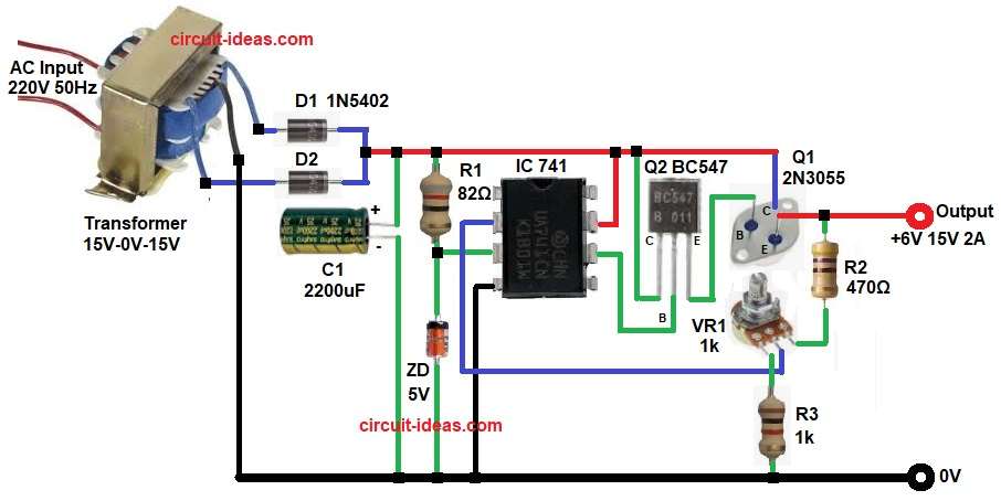
Parts List:
| Components | Values | Quantity |
|---|---|---|
| Resistors | 82Ω 1/4 watt, 470Ω 2 watt, 1k 1/4 watt | 1 each |
| Potentiometer 1k | 1 | |
| Capacitor | Electrolytic 2200uF 25V | 1 |
| Semiconductors | IC LM741 Op-Amp | 1 |
| Power Transistor 2N3055 | 1 | |
| Driver Transistor BC547 | 1 | |
| 5V Zener Diode | 1 | |
| Transformer Secondary 15V-0V-15V 2A Primary 220V AC 50Hz | 1 | |
| Rectifier Diodes 1N5402 | 2 |
First, the 220V AC mains supply enters the transformers primary winding, then the transformer steps the voltage down to 15V-0 V-15V AC at the secondary winding.
After that, two 1N5402 diodes make rectification and it becomes DC voltage, next, C1 2200uF capacitor filter the ripple and so DC becomes smooth.
Now this filtered DC goes to collector of Q1 2N3055 power transistor and at the same time, 5V Zener diode give reference voltage to IC 741 op-amp.
Then op-amp compare reference voltage and output feedback voltage, and if output voltage is low then op-amp increases the output and if output voltage is high then op-amp reduces the output, hence, because of this action the output voltage stay stable.
VR1 adjusts the output voltage from 6V to 15V and Q2 BC547 acts as the driver transistor and supplies sufficient base current to Q1 2N3055, enabling it to deliver the required output current.
Finally, 2N3055 give high current output up to 2A and therefore, we get adjustable and stable DC power supply.
Formulas with Calculation:
This circuit works like non-inverting regulator using feedback divider.
1. Output voltage formula:
Vout = Vref × (1 + R2/R3)
where:
- Vref is 5V for Zener reference voltage
- R2 is Variable resistor VR1 1k potentiometer
- R3 is 1k resistor
Minimum Output Voltage:
When potentiometer R2 = 0 ohm
Vout = 5 × (1 + 0 / 1000)
Vout = 5 × (1 + 0) = 5 × 1 = 5V
But because of transistor drop and circuit design the practical minimum output becomes around 6V.
Maximum Output Voltage:
When potentiometer R2 = 1k
Vout = 5 × (1 + 1000 / 1000)
Vout = 5 × (1 + 1) = 5 × 2 = 10V
Because of the transistor gain and the approximately 18V DC supply available after rectification, the circuit can adjust the output voltage up to about 15V in practice.
2. Power Dissipation of R1:
R1 = 470Ω
Assume voltage drop approx 15V
P = V² / R
P = 15 × 15 / 470 = 225 / 470 = 0.47W
So 2W resistor, used in this circuit for safety.
How to Build:
To build a 6V to 15V Op-Amp Based Power Supply Circuit following are the connection steps one needs to follow:
- Start, the circuit by collecting all the circuit parts as per diagram:
- Then start with IC Pin 7 and connect to positive DC supply.
- Pin 4 connect to ground 0V.
- Pin 3 is connect between 5V Zener diode and resistor R1.
- Pin 2 connect to middle pin of VR1 resistor.
- Pin 6 output of 741 connect to base of Q1 BC547 transistor.
- Next, emitter of Q1 BC547 connect to base of Q1 2N3055, collector of Q2 connect to input of unregulated DC and collector of Q1 2N3055 also connect to unregulated DC and then the emitter of the 2N3055 then provides the final regulated output.
- Now C1 2200uF capacitor connect across DC line for filtering and resistor R2, VR1 and R3 connect from output of 6V to 15V and GND.
- Further, D1 and D2 1N5402 diodes make rectifier from transformer output and transformer primary connect at 220V AC 50Hz and secondary connect 15-0-15V 2A.
Conclusion:
To conclude, this 6V to 15V op-amp based power supply circuit offers a simple, low cost and easy to build solution.
Also, it provides an adjustable output voltage from 6 V to 15 V and delivers an output current of up to 2 A with the help of the 2N3055 power transistor.
Zener diode gives stable reference voltage and op-amp compare reference and feedback voltage; so output remain stable even if load changes.
Therefore, this circuit is good for lab use and is also good for testing small electronic projects and with proper heat sink for 2N3055 transistor circuit works safely and reliably.