This Arduino Entry Exit Monitoring Circuit counts people while entering and leaving place.
It uses Arduino UNO R4 WiFi board.
Two IR sensors detect people.
Two servo motors control entry and exit gates.
Sends crowd count to Arduino IoT Cloud.
Helps know how many people are inside anytime.
Circuit Coding:
#include <Servo.h>
#include "thingProperties.h"

Servo entryServo;
Servo exitServo;

int entrySensor = 2;
int exitSensor = 3;
int count = 0;

void setup() {
Serial.begin(9600);
delay(1500);
initProperties();
ArduinoCloud.begin(ArduinoIoTPreferredConnection);
pinMode(entrySensor, INPUT);
pinMode(exitSensor, INPUT);
entryServo.attach(9);
exitServo.attach(10);
}

void loop() {
ArduinoCloud.update();

if (digitalRead(entrySensor) == HIGH) {
entryServo.write(90);
delay(2000);
entryServo.write(0);
count++;
crowdCount = count;
delay(1000);
}

if (digitalRead(exitSensor) == HIGH) {
exitServo.write(90);
delay(2000);
exitServo.write(0);
count--;
if (count < 0) count = 0;
crowdCount = count;
delay(1000);
}
}
Code Explanation:
- Servo.h library is used to control motors.
- thingProperties.h is Arduino IoT Cloud library.
- entrySensor and exitSensor are IR sensor pins.
- entryServo and exitServo are servo objects.
- If entry sensor detects person then entry servo opens and count increases.
- If exit sensor detects person then exit servo opens and count decreases.
- crowdCount variable sends value to cloud.
Circuit Working:
Parts List:
Person comes near Entry IR sensor and sensor gives HIGH signal.
Arduino moves entry servo and gate opens.
After few seconds servo goes back and gate closes.
Arduino adds people count.
Person comes near Exit IR sensor and sensor gives HIGH signal.
Arduino moves exit servo and gate opens.
After few seconds servo goes back and gate closes.
Arduino reduces people count.
Arduino sends count to IoT Cloud.
We see real-time crowd on dashboard.
Note:
- If needed use two mini breadboards as it depends on how we organize the circuit.
- MG90S servos take more current so keep them on separate breadboard with proper power.
Formulas:
Formula for Arduino Based Entry Exit Monitoring Circuit is shown below:
People Count = Entry Count – Exit Count
If Entry sensor detects signal then Entry Count = Entry Count + 1
If Exit sensor detects signal then Exit Count = Exit Count + 1
Power Supply = 2 x 3.7V = 7.4V
Servo need 5V and Arduino board regulates from VIN.
How to Build:
To build a Arduino Based Entry Exit Monitoring Circuit follow the below steps for connections:
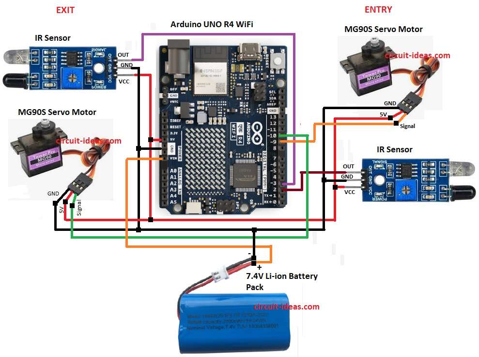
Gather all the parts as shown in circuit diagram:
IR sensor at Entry:
- VCC go to 5V of Arduino
- GND connect to GND of Arduino
- OUT go to digital pin 2
IR sensor at Exit:
- VCC connect to 5V of Arduino
- GND go to GND of Arduino
- OUT go to digital pin 3
Entry Servo Motor:
- Signal(OUT) connects to digital pin 9
- VCC go to 5V of Arduino
- GND go to GND of Arduino
Exit Servo Motor:
- Signal(OUT) go to digital pin 10
- VCC go to 5V of Arduino
- GND connect to GND of Arduino
Battery connection:
- Two 3.7V batteries connected in series to VIN pin of Arduino UNO R4.
- Battery negative to GND pin of Arduino.
Conclusion:
This Arduino Entry Exit Monitoring Circuit counts people in room or hall.
It uses simple IR sensors and servo gates.
Circuit shows crowd data on IoT Cloud.
It is easy and with low cost.
It is used in schools, offices, malls, libraries and events.
Leave a Reply