• Skip to primary navigation
  • Skip to main content
  • Skip to primary sidebar

Circuit Ideas for You

Get free circuit ideas online.

  • Home
  • Privacy Policy
  • About
Home » PIR Motion Detector Circuit using Arduino

PIR Motion Detector Circuit using Arduino

Last updated on 24 June 2026 by Admin-Lavi Leave a Comment

Turn Arduino into a motion spy! with just a PIR sensor, buzzer and LED we can detect movement easily.

Whenever someone passes, it spots movement and warns us with light and sound; this PIR Motion Detector Circuit using Arduino is for beginners and makers.

Also, it is fast to build, fun to use and full of learning.

Arduino Code:

int pirPin = 2;
int buzzer = 3;
int led = 4;
int pirState = LOW;
int val = 0;

void setup() {
pinMode(pirPin, INPUT);
pinMode(buzzer, OUTPUT);
pinMode(led, OUTPUT);
Serial.begin(9600);
}

void loop() {
val = digitalRead(pirPin);
if (val == HIGH) {
digitalWrite(buzzer, HIGH);
digitalWrite(led, HIGH);
if (pirState == LOW) {
Serial.println("Motion detected!");
pirState = HIGH;
}
} else {
digitalWrite(buzzer, LOW);
digitalWrite(led, LOW);
if (pirState == HIGH) {
Serial.println("Motion ended!");
pirState = LOW;
}
}
}

Coding Explanation:

  • pinMode set input or output pins.
  • loop read PIR pin.
  • If PIR is HIGH then buzzer and LED is ON.
  • If PIR is LOW then buzzer and LED goes OFF.
  • pirState used to print message only once on change.

Circuit Working:
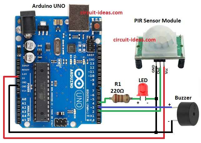
PIR Motion Detector Circuit Diagram using Arduino

Parts List:

ComponentsQuantity
Resistor 220Ω 1/4 watt1
Arduino UNO1
PIR Sensor Module1
Any LED 5mm 20mA1
Buzzer1

The above circuit diagram shows the Arduino motion detector using PIR sensor, LED and buzzer.

Then PIR sensor detect infrared from human body and if motion detects, it send HIGH signal to Arduino pin 2 and Arduino then turn ON buzzer and LED.

After some seconds it turn them OFF again and if there is no motion then buzzer and LED stays OFF.

Formula:

Below is the formula for PIR Motion Detector Circuit:

Use Ohm Law formula : R = V/I

where,

  • R is the resistance in ohms Ω
  • V is the voltage in volts V
  • I is the current in amperes A

How to Build:

To build a PIR Motion Detector Circuit using Arduino follow the below steps for connections:

  • First, gather all the parts as shown in circuit diagram.
  • Next, PIR VCC pin connected to Arduino 5V, PIR GND pin connects to Arduino GND and PIR OUT pin connects to Arduino digital pin 2.
  • Then buzzer positive connect to Arduino pin 3 and buzzer negative connect to GND.
  • After that, LED positive connect to Arduino pin 4 through resistor R1 220 ohm and LED negative connect to GND.
  • Finally, Arduino 5V and GND connect to breadboard power rails.

Conclusion:

Overall, this project is simple PIR Motion Detector Circuit using Arduino, it uses PIR to sense human movement.

Furthermore, Arduino control buzzer and LED alarm and this circuit is also good for home security and for automation.

Filed Under: Arduino Projects, Automation Circuits, Mini Projects, Security and Protection, Sensors and Detectors

About Admin-Lavi

Lavi is a B.Tech electronics engineer with a passion for designing new electronic circuits. Do you have questions regarding the circuit diagrams presented on this blog? Feel free to comment and solve your queries with quick replies

Previous Post: « LDR Light Sensor Circuit with Arduino
Next Post: Arduino Based Electronic Voting Machine Circuit »

Reader Interactions

Leave a Reply Cancel reply

Your email address will not be published. Required fields are marked *

Primary Sidebar


Categories

  • 555 Timer Projects (132)
  • Alarm Circuits (80)
  • Amplifier Circuits (94)
  • Arduino Projects (103)
  • Audio Circuits (189)
  • Automation Circuits (150)
  • Automobile Circuits (40)
  • Battery Charger Circuits (86)
  • DIY Projects (413)
  • Free Energy (12)
  • Heater and Temperature Controllers (32)
  • High Voltage (24)
  • Hobby Circuits (229)
  • Indicator Circuits (63)
  • Inverter Circuits (17)
  • IoT projects (12)
  • LDR Circuits (47)
  • LED and Lamps (201)
  • Meters and Testers (44)
  • Mini Projects (372)
  • Motor Controllers (25)
  • Oscillator Circuits (70)
  • Power Supply Circuits (240)
  • Radio Frequency (8)
  • Remote Control Circuits (12)
  • Renewable energy (20)
  • Security and Protection (127)
  • Sensors and Detectors (234)
  • Solar Circuits (31)
  • Timer Circuits (62)
  • Transistor Circuits (178)
  • Transmitter Circuit (19)
  • Tutorials (31)
  • Voltage Regulator (43)
  • Water Level Controller (10)

Recent Posts

  • Low Current Controlled Battery Charger Circuit using LM723 IC
  • 741 Op-Amp Treble Booster Circuit
  • Simple Diode and Transistor Based Audio Limiter Circuit
  • Simple 500mW Speaker Driver Circuit
  • Easy DIY LM386 Audio Amplifier Circuit

Recent Comments

  1. Admin-Lavi on High Voltage Fence Charger Circuit
  2. egidio grzinic on High Voltage Fence Charger Circuit
  3. Logic OR Gate Circuit using Transistors - Circuit Ideas for You on Automatic Street Light Circuit using LDR
  4. Tony Gallegos on NTC Thermistor Based Temperature to Voltage Converter Circuit
  5. colin on Simple Single Transistor Audio Amplifier Circuit

Copyright © 2026 | New Circuit Ideas