This project is for small Electronic Eye Circuit using IC 4049, which can sense darkness or shadow.
When light falls on the LDR, the circuit remains OFF and when an object blocks the light, the LED and buzzer turns ON; moreover, this circuit also works like a magic eye and is useful for security systems and door alarms.
Circuit Working:
Parts List:
| Components | Values | Quantity |
|---|---|---|
| Resistors | 100k 1/4 watt | 1 |
| LDR standard | 1 | |
| Semiconductors | IC CD4049 Hex Inverter | 1 |
| Buzzer 5V | 1 | |
| LED 5mm 20mA any color | 1 |
The main brain of the circuit is NOT gate and it comes from CD4049 CMOS IC, as this IC has six NOT gates and also in this circuit we have used only one gate
Here, LDR and resistor R1 form a voltage divider and LDR resistance is low in light and high in dark.
The IC CD4049 is a hex inverter that changes a logic high to a logic low and a logic low to a logic high; in addition, pin 14 serves as the input of the inverter gate and pin 15 provides the output.
When light falls on LDR, voltage at input is low and inverter output becomes high, so buzzer and LED are OFF and when darkness comes, voltage at input increases, inverter output goes low and turning buzzer and LED ON.
So circuit works opposite of light presence.
Formulas:
Below is the formula for Electronic Eye Circuit using IC 4049 :
Voltage at input (Vinput) = (R1 / (R1 + RLDR)) * Vcc
If light is strong then RLDR is small (few hundred ohms) so Vinput is small and if dark then RLDR is large few mega ohms, so Vinput is large.
Hence, IC 4049 changes this voltage to opposite logic.
How to Build:
To build an Electronic Eye Circuit using IC 4049 follow the below connection steps:
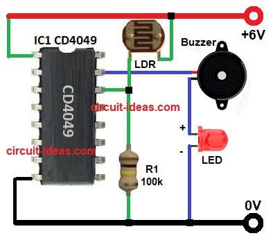
- First, assemble all the parts as shown in circuit diagram.
- Next, connect +6V to pin 1 Vcc and pin 8 to ground.
- Then pin 14 input connect from junction of one end of LDR and one end of resistor R1.
- After that, pin 15 output connect to one end of buzzer and other end to one end of LED and other end of LED connect to GND.
- Also, connect other end of LDR to +6V and connect other end of resistor R1 100k to ground.
Conclusion:
This Electronic Eye Circuit using IC 4049 easily detects light and darkness, and we can use it as a door alarm, shadow detector or night sensor;
Also, the circuit requires only a few components, costs little and is easy to build and operates with a 6 V battery or a DC adapter.
Leave a Reply