This project shows about an easy and simple LM350 Based 24V 3A Voltage Regulator Circuit.
The circuit converts AC mains into stable DC output, and also this design suits small lab use, battery charging and general electronics work.
Moreover, LM350 gives adjustable output with good current capability, therefore by adjusting potentiometer we can get around 24V and up to 3A current with proper heat sink.
Circuit Working:
Parts List:
| Components | Values | Quantity |
|---|---|---|
| Resistors | 2.2k, 270Ω 1/4watts | 1 each |
| Potentiometer 5k | 1 | |
| Capacitors | Electrolytic 6800µF 50V, 220µF 35V, 47µF 35V | 1 each |
| Ceramic 0.01µF | 2 | |
| Semiconductors | IC LM350 | 1 |
| Heatsink for IC LM350 | 1 | |
| Any standard LED | 1 | |
| Diode 1N4007 | 2 | |
| Bridge Diode 6A 100V | 1 | |
| Transformer primary 220V AC 50Hz, Secondary 0V-24V AC 5A | 1 | |
| Switch ON/OFF Switch | 1 | |
| Fuse 0.5A | 1 |
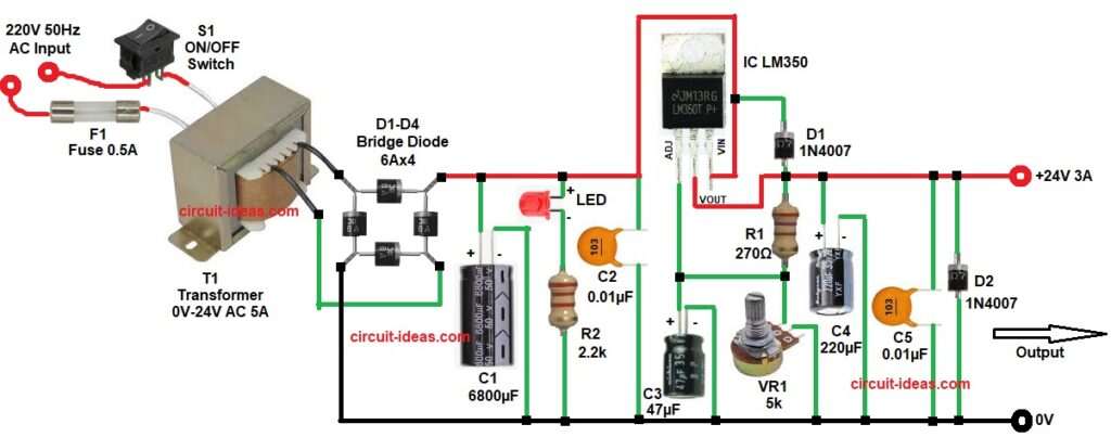
First, AC input 220V enters through switch S1 and fuse F1, then transformer T1 steps down voltage to 24V AC.
After that, bridge rectifier converts AC into pulsating DC, next, capacitor C1 filters the ripple and gives smooth DC around 34V.
After filtering, the DC goes to LM350 input pin, meanwhile, diode D1 protects the regulator from reverse current and also, small capacitor C2 removes noise.
Now, LM350 regulates voltage based on R1 and VR1 and when we rotate VR1, output voltage changes, then capacitor C3 improves stability at adjust pin.
At output side, capacitor C3 220uF and C4 0.01uF smooth the final DC.
Also, diode D2 protects load and regulator during reverse condition and finally, the circuit gives stable 24V output up to 3A.
Formula with Calculation:
LM350 output formula:
Vout = 1.25 × (1 + R2(VR1) / R1) + Iadj × R2(VR1)
here,
- Vout is the output voltage
- 1.25 is the internal reference voltage of LM350
- R1 is the resistor connected between output and adjust pin
- R2(VR1) in circuit diagrmVR1 is the potentiometer connected between Adjust pin and Ground
- Iadj is small adjust pin current very small which is usually ignored
- R2(VR1) / R1 sets how much voltage increases above 1.25V
Values as per circuit:
R1 = 270 ohm
VR1 = 5k potentiometer
For approx 24V output:
24 = 1.25 × (1 + R2 / 270)
Now we can solve:
24 / 1.25 = 1 + R2(VR1) / 270
19.2 = 1 + R2(VR1) / 270
18.2 = R2(VR1) / 270
R2(VR1) = 4914 ohm (approx 4.9K)
So, VR1 is around 5k used in the circuit, gives adjustable output near 24V.
How to Build:
To build LM350 Based 24V 3A Voltage Regulator Circuit follow the below connection steps:
- Start, the circuit by gathering all the circuit parts as in diagram above.
- First, connect transformer primary through fuse and switch to secondary side.
- Then connect the secondary side to to bridge rectifier input.
- And connect bridge output to filter capacitor C1.
- Then connect LED with resistor R2 for power indication.
- After that connect capacitor C2 from input pin of IC and gnd.
- Next, connect diode D1 from output pin to input pin of IC.
- Then start with LM350 IC with input pin connect to filtered DC.
- Next, connect output pin to load output terminal of 24V.
- Then connect adjust pin to junction of R1 and VR1.
- Connect capacitor C3 positive from adjust pin of IC and negative of capacitor goes to GND.
- Now, connect output capacitors C4 and C5 across output and ground.
- Finally, also connect diode D2 from output to ground.
Conclusion:
To conclude, this circuit gives simple and reliable 24V 3A DC supply.
Also, LM350 makes voltage adjustable and stable, however, we must use proper heat sink because power loss is high.
Therefore, this design works well for medium power applications and overall, it is easy to build and useful for beginners and students.
Leave a Reply