To begin with, this project is about a simple 12V Dynamic Mic Preamplifier Circuit which uses two NPN transistors BC549 and to increase very small audio signal from a dynamic microphone.
Moreover, the circuit gives enough gain so we can feed the signal to an amplifier or recording system and also it works on 12V DC supply with a low cost and easy to build.
Circuit Working:
Parts List:
| Components | Values | Quantity |
|---|---|---|
| Resistors (All resistors are 1/4 watt) | 390k, 680Ω,100k, 10k,1k | 1 each |
| 220k | 2 | |
| Capacitors | Electrolytic 1µF 50V, 2.2µF 25V, 100µF 25V | 1 each |
| Electrolytic 4.7µF 25V | 2 | |
| Ceramic 100pF 50V | 1 | |
| Semiconductors | Transistors BC549 or BC547 | 2 |
| Power Supply 12V DC | 1 |
The above circuit has two stages.
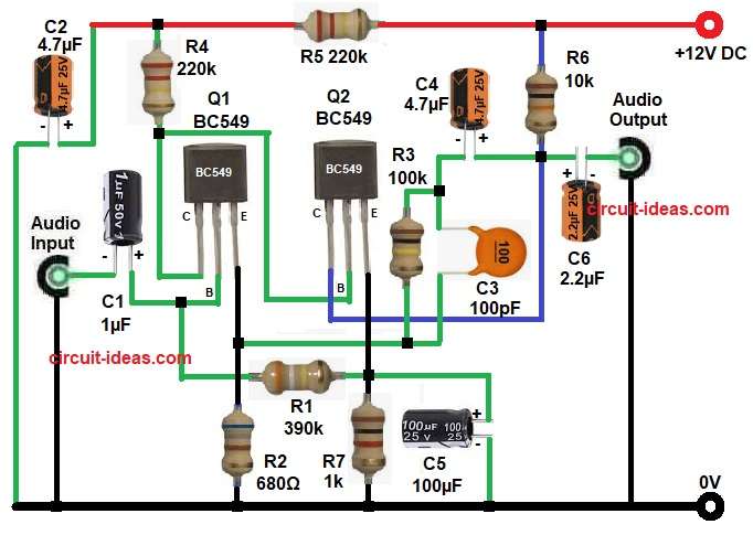
First stage, uses Q1transistor, the microphone signal comes through capacitor C1 and this capacitor blocks DC and allows only audio signal.
Then R1 gives bias to base of Q1, R2 works as emitter resistor and Q1 amplifies weak input signal.
After that R4 is collector resistor for Q1, C2 works as supply filter and reduces noise and output of first stage goes to second stage through capacitor C4.
Next, is the second stage, which uses Q2 transistor, R3 gives base bias for Q2, R7 is emitter resistor for Q2 and C5 bypasses emitter resistor so gain increases.
Then R6 is collector resistor of Q2 and output signal comes from collector through capacitor C6, hence, this capacitor again blocks DC and passes audio signal.
Furthermore, capacitor C3 is a small capacitor for stability which reduces high frequency noise and prevents oscillation.
Overall, first transistor gives initial gain, second transistor boosts the signal more and so final output is strong and clean.
How to Build:
To build a 12V Dynamic Mic Preamplifier Circuit follow the below connection steps:
- Start, by gathering all the circuit parts as in diagram above.
- Next, start with transistor BC549 Q1 base pin go one end of resistor R1 and positive of capacitor C1.
- Then collector pin go to one end of resistor R4 and base of transistor Q2.
- After that, emitter pin connect to the junction of resistor R2, R3 one end and capacitor C3 one end.
- Next, take transistor Q2 BC549 and connect base pin between collector of Q1 and resistor R4.
- Then, collector pin connect to the junction of resistor R6 one end and capacitor C4 and C6 positive end.
- After that, emitter pin connect to the junction of resistor R1 and R7 one end and capacitor C5 positive end.
- Next, connect capacitor C2 and resistor R5 in series from positive supply and ground.
- Also, connect audio input from negative of capacitor C1 and ground.
- Lastly, audio output connect from capacitor C6 negative end and ground.
Conclusion:
This 12V Dynamic Mic Preamplifier Circuit is simple and useful project which gives good gain for dynamic microphones.
Also, it uses common parts and easy wiring where beginners can build it easily, moreover, we can use it in audio projects, recording and small amplifiers.
Leave a Reply