To begin with, a Active Crossover Circuit using IC LM324 is an important project for audio, as it split audio signal into parts like low, mid and high.
Each part go to right speaker with woofer for bass and tweeter for high, also this make sound better and system works well.
People widely use the IC LM324 op-amp because it is cheap, consumes low power and works with both single and dual power supplies.
This article also explains how to make and use an active crossover with the LM324 IC.
Circuit Working:
Parts List:
| Components | Values | Quantity |
|---|---|---|
| Resistors | 22k 1/4 watt | 7 |
| 6.2k 1/4 watt | 2 | |
| Capacitors | 6.8nF | 3 |
| Semiconductor | IC LM324 | 1 |
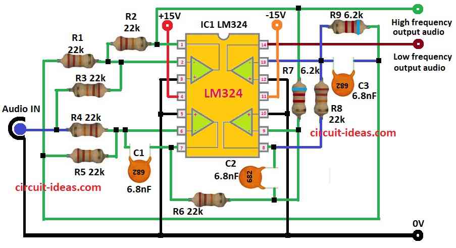
This circuit is 2nd order active crossover using LM324 chip and it split audio into two parts:
- High frequency output
- Low frequency output
Also, it uses op-amps in LM324 with resistors and capacitors to set crossover point.
Input Stage:
- First op-amp is buffer and it protect input and prepare signal.
High Frequency Filter:
- Second op-amp is high-pass filter with R3, R5, C1 and it passes high sounds and block low.
- Output give high frequency signal.
Low Frequency Filter:
- Third op-amp is low-pass filter with R6, R8, C2 and it passes low sounds and block high.
- Output give low frequency signal.
Final Amplification:
- Fourth op-amp make low sound stronger before output.
Good Points:
- Circuit is simple and is cheap design
- Only one LM324 IC used.
- Can change crossover by changing resistor/capacitor and it works with ±15V dual power for better sound
Where to Use:
- Audio systems, home theater and studio
- Loudspeakers and PA systems
- Communication devices for sound filtering
Formulas and Calculations:
Formulas for Active Crossover with LM324:
High Pass Filter:
Cutoff frequency (ƒc) use this formula:
ƒc = 1 / 2πRC
where:
R = R5 is 22k
C = C1 is 6.8nF
Put values in formula:
ƒc = 1 / (2π × 22,000 × 6.8 × 10⁻⁹)
ƒc = 1.06 kHz
Same formula and same values:
R = R8 is 22k
C = C2 is 6.8nF
Put values:
ƒc = 1 / (2π × 22,000 × 6.8 × 10⁻⁹)
ƒc = 1.06 kHz
So crossover frequency is around 1.06 kHz and this help split high and low signals clearly in circuit.
How to Build:
To build a Active Crossover Circuit using IC LM324 follow the below mentioned steps for connections:
- First, collect all parts as shown in circuit diagram.
- Next, connect pin 4 of LM324 to +15V and pin 11 to –15V with dual power.
- Then audio input goes to pin 3 with non-inverting of first op-amp.
- Put resistor R1 between pin 2 of inverting input and then connect resistor R2 between pin 1 output and pin 2 of inverting input.
- Also, connect pins 3, 5, 10, 12 to GND.
- After that, connect capacitor C1 6.8nF and resistor R5 in parallel to pin 6 of inverting input and pin 7 gives high frequency output.
- Now, from pin 1 go to pin 9 of non-inverting of third op-amp using resistor R7.
- Further, connect capacitor C2 6.8nF and resistor R8 in parallel to pin 10 of inverting input.
- Pin 8 gives output to next stage and then connect pin 8 which is the low signal to pin 13 of inverting input of fourth op-amp using resistor R9.
- Next, put capacitor C3 6.8nF and resistor R7 between pin 14 of output and pin 13 and finally, pin 14 gives low frequency output.
Conclusion:
To conclude, this Active Crossover Circuit using IC LM324 is smart and useful project, it is easy to make with low cost and is good for many audio projects.
Also, it splits sound nicely and helps each speaker play better.
Leave a Reply