Nickel Metal Hydride (Ni-MH) batteries are popular for small devices because they provide good power and are rechargeable, so to ensure a long lifespan, we must use proper charging methods.
The Ni-MH Battery Charger Circuit with IC LT4060 is a powerful charger that uses the LT4060 IC from Linear Technology and this IC efficiently charges 1.2V Ni-MH batteries.
Also, this article explains the charger circuit, how it works, its key formulas, how to build it and the final tips.
Circuit Working:
Parts List:
| Components | Values | Quantity |
|---|---|---|
| Resistors | 330Ω 1/4 watt , 680Ω + 18 = 698Ω 1/4 watt | 1 each |
| Preset 10k | 1 | |
| NTC Thermistor 10k | 1 | |
| Capacitors | Ceramic 1.5nF | 1 |
| Semiconductors | IC LT4060 | 1 |
| Transistor 2N2907 | 1 | |
| Battery Ni-MH in series 1.2V | 2 |
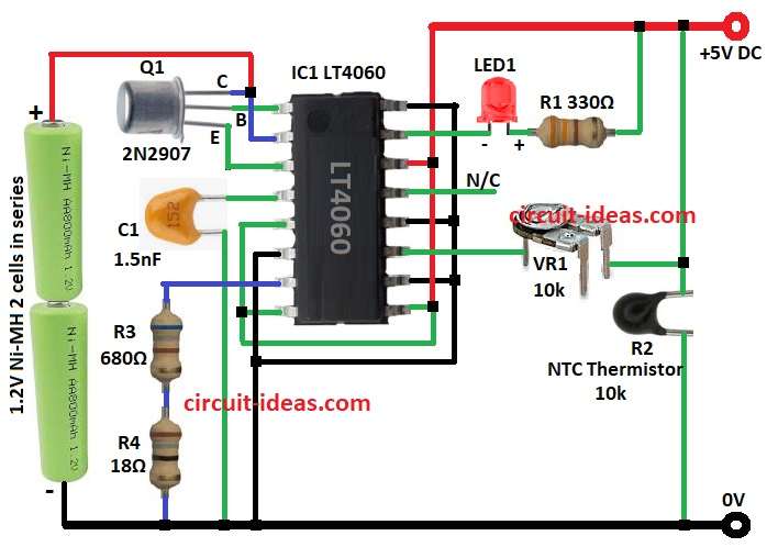
The circuit uses 5V DC power to Vcc pin of LT4060 chip and this chip controls charging current using DRIVE pin and Q1 2N2907 transistor.
Then charging current depends on resistors R3 and R4 and NTC thermistor R2 checks battery temperature and iIf battery is too hot then chip stops charging to protect it.
Now LT4060 uses smart charging and first gives constant current till set voltage and then it changes to trickle charge to keep battery full.
After that, timer capacitor C1 sets the maximum charging time to prevent overcharging and we calculate the time using the special formula below.
Formulas and Calculations:
Below are simple formulas and values for Ni-MH battery charger:
Charging Current (Icharge):
Set by R3 and R4:
Icharge = 1000 / (R3 + R4) (in Amps)
If R3 = 680Ω and R4 = 18Ω
Icharge = 1000 / 698 = 1.43 mA
Charging Time (Tcharge):
Set by capacitor C1:
Tcharge = 3 × C1 × 10⁶ (in seconds)
If C1 = 1.5 nF
Tcharge = 3 × 1.5 × 10⁻⁹ × 10⁶ = 4.5 seconds
Battery Voltage (Vbattery):
Vbattery = N × Vcell
If N = 2 cells and Vcell = 1.2V
Vbattery = 2 × 1.2 = 2.4V
How to Build:
To build a Ni-MH Battery Charger Circuit follow below steps for building and connections:
- First, gather all the components as per the circuit diagram
- Next, pin 1 (DRIVE) goes to base of Q1 and Q1 collector goes to pin 2 (BATTERY) and then Q1 emitter goes to pin 3 (SENSE)
- Then pin 4 (TIMER) goes to one side of C1 and other side of C1 goes to GND
- After that, pin 5 (SHDN) ,pin 8 (ARCT), pin 9 (SELO) and pin 14 (VCC) goes to +5V DC
- Now pin 6 (PAUSE), pin 10 (SEL1), pin 12 (CHEM) and pin 16 (GND) go to GND
- Further, pin 7 (PROG) go to R3 and R4 in series go to GND
- Also, pin 11 (NTC) goes to one leg of VR1 and other leg of VR1 go to +5V and R2 go to GND
- Do not connect pin 13 (ACP).
- Then pin 15 (CHRG) goes to negative of LED1 and positive of LED1 goes to R1 and +5V DC
Conclusion:
To conclude, this Ni-MH Battery Charger Circuit with IC LT4060 is simple and works well, as it has safety, checks temperature and time so battery stays safe.
Also, it is good for toys, gadgets and backup systems and if build correct then it gives strong and safe charging.
Thanks 🙂