What if charger is smart? and if it fills battery by itself and keeps it full, but not too much.
That is what Automatic Battery Charger with Trickle Charger Circuit does; it has part that checks battery power and if battery is low it sends power to fill.
When it is full it gives little power slowly like a tiny sip to keep battery good and this way battery stays healthy and lasts longer.
Circuit Working:
Parts List:
| Components | Values | Quantity |
|---|---|---|
| Resistors | 1/4 watt unless specified | |
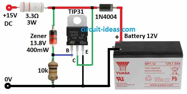
| 10k 1/4 W | 1 | |
| 3.3Ω 3W | 1 | |
| Semiconductors | Transistor TIP31 | 1 |
| Zener Diode 13.8V, 400mW | 1 | |
| Diode 1N4004 | 1 | |
| Battery 12V | 1 |
This circuit keeps battery full automatically and when battery reaches 13.8V its charging slows down and also the battery stays ready to use and charger keeps it full.
Furthermore, transistor works like Zener diode with13.8V and this Zener goes to base and stops power from going over 14.4V means 13.8 + 0.6V.
1N4004 diode drops 0.6V so battery gets 13.8V and if power supply is strong which is over 16V with no load then we should use 3.3 ohm 3 watt resistor.
Also, transistor turns extra charge into heat to protect battery.
Formulas:
We can use some simple formulas to understand this circuit better.
Voltage Divider R1 and R2:
These resistors control the voltage going to the base of transistor TIP31 and this helps manage battery charging.
The formula for base voltage (Vb) is:
Vb = Vin × (R2 / (R1 + R2))
where:
- Vb is voltage at transistor base TIP31
- Vin input voltage from power source
Note:
It is best to use a proper charger made for our battery type and it is safer and charges our battery the right way with safety features built in.
How to build:
To build a Automatic Battery Charger with Trickle Charger Circuit follow the below mentioned connections process:
- First, connect base of TIP31 transistor to a Zener diode and 10k resistor in series.
- Next, one side of Zener diode goes to positive supply and the other side goes to ground through 10k resistor.
- Then connect collector of TIP31 to positive supply, emitter of TIP31 to ground.
- After that connect positive side of 12V battery through 1N4004 diode and 3.3Ω resistor to DC output and connect negative side of battery to ground.
Safety Tips:
- Always double check wires and connections before turning ON the power and wear safety gear like gloves and goggles.
- Keep the circuit dry, keep it away from water and do not touch it while it has power.
- Unplug when not in use.
Conclusion:
To conclude, this Automatic Battery Charger with Trickle Charger Circuit helps keep battery healthy, it adjusts charging by checking battery voltage with no overcharging!
Hence, the trickle charge keeps the battery full and ready to use; therefore, this type of circuit works well in many battery-powered projects.
Leave a Reply