Amplifiers make heat when working, also too much of heat make it work bad and can die soon; therefore, this Temperature Controlled Fan Circuit for Audio Amplifiers keep amplifier cool.
Fan starts only when amplifier is hot and if volume is low and less heat then fan stays OFF and saves power.
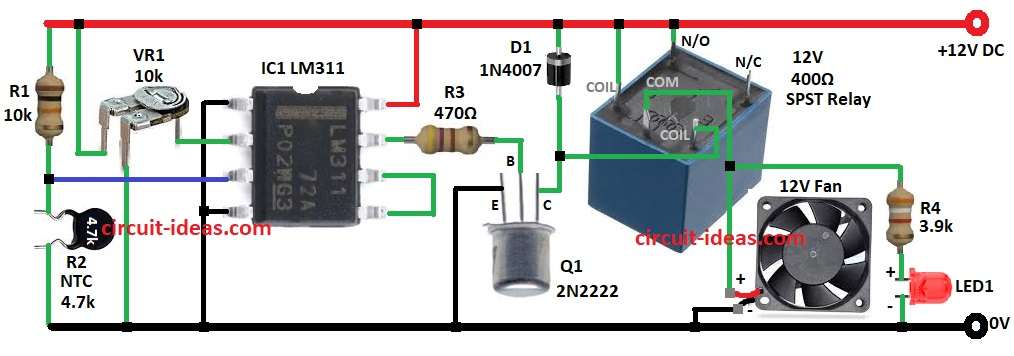
Also, the circuit uses an LM311 comparator IC, a 2N2222 transistor, an NTC thermistor and a 12V relay and it requires a 12V DC power supply to operate.
Circuit Working:
Parts List:
| Components | Values | Quantity |
|---|---|---|
| Resistors | 10k 1/4 watt | 1 |
| 470Ω 1/4 watt | 1 | |
| 3.9k 1/4 watt | 1 | |
| Thermistor NTC 1k to 4.7k | 1 | |
| Preset 10k | 1 | |
| Semiconductors | IC LM311 | 1 |
| Transistor 2N2222 | 1 | |
| Diode 1N4007 | 1 | |
| Fan 12V | 1 | |
| Relay 12V SPST 400Ω | 1 | |
| LED 5mm 20mA | 1 |
R2 NTC thermistor and R1 make voltage divider and this give voltage that change with heat to pin 3 (inverting) of LM311.
Then VR1 provides a fixed voltage to pin 2 (non-inverting input).
When temperature goes up the thermistor resistance goes down and voltage at pin 3 drops and if pin 3 voltage is lower than pin 2 then LM311 IC output pin 7 goes LOW.
Hence, this turns ON the Q1 transistor and Q1 turns ON 12V relay and relay start 12V fan to cool the amplifier.
Finally, D1 diode protect relay from spikes and LED1 with R4 show fan is ON.
Formulas with Calculations:
The following formulas and calculations explain the Temperature Controlled Fan Circuit for Audio Amplifiers:
V divider with thermistor R2 and R1 formula:
V_NTC = (R2 / (R1 + R2)) * V_supply
Comparator:
If V_NTC < V_ref set by VR1 comparator flips and turns transistor ON.
Relay transistor base:
I_B = (V_output – V_BE) / R3
Relay coil current collector:
I_C = V_relay / R_relay
Fan power:
P = V * I
Example: 12V x 0.2A = 2.4W
How to Build:
To build a Temperature Controlled Fan Circuit for Audio Amplifiers follow below steps for connection:
- First, assemble parts like in circuit diagram.
- Next, pin 1 of LM311 IC goes to GND
- After that, pin 2 goes to middle of VR1 and top of VR1 connects to +12V and bottom pin goes to GND
- Now pin 3 connects between R1 and R2
- Also, pin 4 connects to GND
- Further, pin 5 connects to pin and pin 7 goes to base of Q1 through R3, Q1 collector connects to +12V through D1 and then Q1 emitter connects to GND
- Then pin 8 goes to +12V
- Now relay coil one side connects to +12V and other side connects to Q1 collector, relay N/O connects to +12V, COM connects to one side of 12V fan and other side of fan connects to GND
- Finally, R4 one side connects between COM and fan and other side goes to LED1 anode and LED1 cathode goes to GND
Conclusion:
To conclude, this Temperature Controlled Fan Circuit for Audio Amplifiers keeps amplifier cool automatically, it uses NTC and LM311 IC to start fan only when hot.
Also, the circuit saves energy and stops overheating and it is good for amplifies and other heat sensitive gear.
Leave a Reply