A Simple Adjustable Frequency Square Wave Generator Circuit provides an easy and flexible solution for signal processing, modulation and many electronic projects.
Here we see variable frequency oscillator using 555 timer IC which makes square waves and where user can change frequency; also 555 works in astable mode and turning potentiometer changes output speed.
Circuit is good for making waveforms, clock pulses and for testing circuits and it gives few Hz to many kHz and works with 5V to 15V power.
Circuit Working:
Parts List:
| Components | Values | Quantity |
|---|---|---|
| Resistor | 1k 1/4 watt | 1 |
| Potentiometer 1M | 1 | |
| Capacitors | Ceramic 0.01µF | 2 |
| Semiconductor | IC 555 Timer | 1 |
Circuit works in astable mode and IC 555 keeps switching high and low by making square wave; also frequency set by R1, VR1 and C1.
Then C2 keeps voltage stable and if required turn VR1 to change resistance, which changes 555 cycle time and frequency.
Formulas with Calculations:
Output frequency (f) and duty cycle (D) of 555 in astable mode:
Formulas:
f = 1.44 / ((R1 + 2VR1) × C)
T = 0.693 × (R1 + 2VR1) × C
T1 = 0.693 × (R1 + VR1) × C
T2 = 0.693 × VR1 × C
where:
- f is the frequency in Hz
- T is the time period
- T1 is the high time
- T2 is the low time
- R1 is 1kΩ resistor
- VR1 is 1MΩ potentiometer
- C1 is 0.01µF capacitor
How to Build:
To build a Simple Adjustable Frequency Square Wave Generator Circuit follow the below mentioned steps:
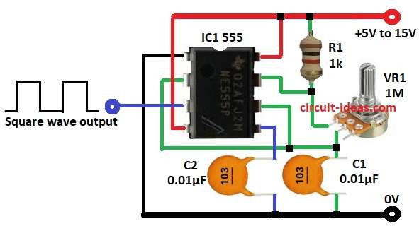
- First, assemble parts like in circuit diagram:
- Next, pin 1 connected to GND
- Then pin 2 joined to pin 6
- After that, pin 3 connected to square wave output
- Now pin 4 and pin 8 connected to +5V to +15V supply
- Also, pin 5 connected to GND through C2
- Further, R1 connected between +V and pin 7
- Then VR1 connected between pin 7 and pin 2 and 6
- Finally, C1 connected between pin 2 and GND
Conclusion:
Overall, Simple Adjustable Frequency Square Wave Generator Circuit is a useful project for beginners; turn potentiometer knob to change the speed.
Also, the circuit is good for function generator, PWM, clock pulses and is easy to build with few parts and is good for beginners and experts.
Leave a Reply