This project show how to make a simple Arduino Based Pulse Monitoring Circuit.
It uses Arduino Nano, pulse sensor, OLED display, buzzer, an LED.
The system reads heartbeat from finger sensor.
Then Arduino calculate pulse per minute.
OLED show result.
LED and buzzer give alert when pulse go high or low.
Circuit is simple and with low power.
Good for beginners and students.
Arduino Coding:
#include <Wire.h>
#include <Adafruit_GFX.h>
#include <Adafruit_SSD1306.h>

Adafruit_SSD1306 display(128, 64, &Wire);

int pulsePin = A0;
int ledPin = 7;
int buzzerPin = 8;

int signal;
int threshold = 550;
boolean pulse = false;
unsigned long lastBeat = 0;
int bpm = 0;

void setup() {
pinMode(ledPin, OUTPUT);
pinMode(buzzerPin, OUTPUT);
display.begin(SSD1306_SWITCHCAPVCC, 0x3C);
display.clearDisplay();
display.display();
}

void loop() {
signal = analogRead(pulsePin);

if (signal > threshold && pulse == false) {
pulse = true;
unsigned long nowTime = millis();
unsigned long gap = nowTime - lastBeat;
lastBeat = nowTime;
if (gap > 0 && gap < 2000) {
bpm = 60000 / gap;
}
}

if (signal < threshold) {
pulse = false;
}

display.clearDisplay();
display.setTextSize(2);
display.setTextColor(WHITE);
display.setCursor(0,0);
display.print("BPM:");
display.print(bpm);
display.display();

if (bpm > 100 || bpm < 50) {
digitalWrite(ledPin, HIGH);
digitalWrite(buzzerPin, HIGH);
} else {
digitalWrite(ledPin, LOW);
digitalWrite(buzzerPin, LOW);
}

delay(20);
}
Coding Explanation:
- PulsePin read sensor value.
- Threshold detect heart peak.
- When peak appear Arduino calculate time gap.
- Using gap Arduino make BPM.
- Display code show BPM on OLED.
- If BPM is too high or low buzzer and LED turn ON.
- If BPM is normal both are OFF.
- Delay is used for stable reading.
Circuit Working:
Parts List:
| Item | Quantity |
|---|---|
| Resistor 220Ω 1/4 watt | 1 |
| Arduino Nano | 1 |
| Pulse Sensor Module | 1 |
| OLED Screen 1306 | 1 |
| LED any | 1 |
| SPST switch On Off | 1 |
| Buzzer | 1 |
| 9V Battery | 1 |
In this circuit pulse sensor give small voltage change when heart beat.
Arduino read this change at analog pin.
Arduino measure time gap between peaks.
From this time gap Arduino calculate beats per minute.
OLED show live BPM(Beats Per Minute).
When BPM cross set value, LED turn ON and buzzer beeps.
The resistor R1 limits the current and keeps the LED safe.
When BPM is normal again both turn OFF.
A switch in the circuit makes it easier to turn the whole project ON and OFF.
9V battery give portable power to the Arduino and the whole pulse monitoring circuit.
Formula with Calculation:
Below is the general formula commonly used in Arduino pulse sensor projects.
BPM formula:
BPM = 60000 / time_between_beats_in_milliseconds
Example:
If time between beats = 750 ms
BPM = 60000 / 750
BPM = 80
80 BPM is normal heart rate, not too high and not too low.
How to Build:
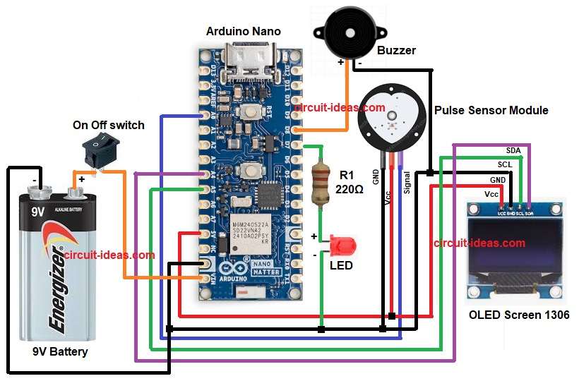
To build a Arduino Based Pulse Monitoring Circuit follow the connection steps below:
- Gather all the parts as shown in circuit diagram.
- Arduino Nano 5V goes to OLED VCC and pulse sensor VCC.
- Arduino Nano GND goes to OLED GND and pulse sensor GND
- OLED SDA go to A4 pin.
- OLED SCL go to A5 pin.
- Pulse sensor signal wire go to A0 pin.
- Buzzer positive connect to D8 pin and negative to GND.
- LED positive goes through resistor to D7 pin and negative to GND.
- Battery positive connect to Vin pin of Arduino Nano
- And battery negative connect to GND.
- Connect switch to 9V battery positive.
Conclusion:
This Arduino Based Pulse Monitoring Circuit is low cost and easy to build.
Good for school project.
Not a medical device but useful for hobby use.
Using Arduino make code easy to change.
We can add Bluetooth or SD card later.
It is simple and work fine for learning heartbeat sensing.
Leave a Reply