Railway accidents happen because obstacles come on railway track, because many trains cannot stop fast; therefore, this project uses Arduino Uno, ultrasonic sensor, relay and motor or servo to give warning or stop mechanism.
The system checks distance and if object comes close, relay activates and motor moves barrier or alarm system, also this helps to avoid accidents in simple low-cost way.
Additionally, this Railway Track Accident Prevention Circuit using Arduino is easy to build.
Arduino Code:
const int trigPin = 9;
const int echoPin = 10;
const int relayPin = 7;
const int servoPin = 6;

long duration;
int distance;

#include <Servo.h>
Servo myservo;

void setup() {
pinMode(trigPin, OUTPUT);
pinMode(echoPin, INPUT);
pinMode(relayPin, OUTPUT);
myservo.attach(servoPin);
myservo.write(0);
digitalWrite(relayPin, LOW);
Serial.begin(9600);
}

void loop() {
digitalWrite(trigPin, LOW);
delayMicroseconds(2);
digitalWrite(trigPin, HIGH);
delayMicroseconds(10);
digitalWrite(trigPin, LOW);

duration = pulseIn(echoPin, HIGH);
distance = duration * 0.034 / 2;

Serial.println(distance);

if (distance < 20) {
digitalWrite(relayPin, HIGH);
myservo.write(90);
} else {
digitalWrite(relayPin, LOW);
myservo.write(0);
}
delay(200);
}
Coding Explanation:
- Ultrasonic sensor sends sound pulse.
- Echo pin reads back the signal time.
- Arduino calculates distance from time.
- If distance is less than set value like 20 cm then Arduino turns relay ON.
- Servo also rotates to show barrier movement.
- If distance is safe then relay stays OFF and servo goes back.
- Simple logic control.
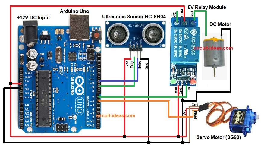
Circuit Working:
Parts List:
| Components | Quantity |
|---|---|
| Arduino Uno | 1 |
| Ultrasonic Sensor HC-SR04 | 1 |
| 5V Relay Module | 1 |
| Servo Motor (SG90) | 1 |
| DC Motor | 1 |
Arduino gives 5V power to ultrasonic sensor and to servo, trig pin sends pulse and echo pin reads reflection.
Then relay module gets 5V and signal from Arduino digital pin and also this relay can drive a DC motor or alarm.
Hence, when the sensor detects an object nearby, the relay activates and starts the motor or alarm, then, the servo rotates to show the gate closing.
Finally, all devices share common ground.
Formulas:
Ultrasonic distance formula:
Distance = (time x speed of sound) / 2
Speed of sound in air approx 340 meter per second
In microseconds speed about 0.034 cm per microsecond
So distance = duration x 0.034 / 2
Division by 2 because pulse travels to object and back.
How to Build:
To build a Railway Track Accident Prevention Circuit using Arduino follow the below steps:
- First, gather all the parts as shown in circuit diagram.
- Next, Ultrasonic sensor VCC pin go to 5V, GND pin go to GND, Trig pin go to Arduino pin 9 and echo pin go to Arduino pin 10.
- Then relay module VCC pin go to 5V, GND pin go to GND, Signal IN pin go to Arduino pin 7 and COM pin goes to +5V of Arduino
- Now relay output terminals go to motor
- Further, servo motor Red wire go to 5V, brown wire go to GND, orange or yellow wire go to Arduino pin 6.
- Lastly, connect one wire of the DC motor to the relays NO (Normally Open) terminal and connect the other wire to the Arduino GND.
Conclusion:
To conclude, this project for Railway Track Accident Prevention Circuit using Arduino gives simple method to avoid railway accidents.
Here, system detects object on track using ultrasonic sensor and then Arduino controls relay and servo to give warning or close barrier.
This project costs very little and works reliably, also we can install it on small rail crossings or demo models because it increases safety and reduces human error.
Leave a Reply