This article show how to make a simple Arduino Battery Charger Circuit.
Here, charger stop and start charging using MOSFET and then Arduino read battery temperature with TMP36 sensor and decide safe charging.
Additionally, circuit is simple and work with basic components.
Arduino Code:
int tempPin = A1;
int mosfetPin = 9;
float voltage = 0;
float temperatureC = 0;

void setup() {
pinMode(mosfetPin, OUTPUT);
digitalWrite(mosfetPin, LOW);
}

void loop() {
int sensorValue = analogRead(tempPin);
voltage = sensorValue * (5.0 / 1023.0);
temperatureC = (voltage - 0.5) * 100.0;

if (temperatureC < 40) {
digitalWrite(mosfetPin, HIGH);
} else {
digitalWrite(mosfetPin, LOW);
}

delay(500);
}
Code Explanation:
- tempPin store A1 pin number.
- mosfetPin store D9 pin number.
- Arduino read analog value from TMP36.
- Convert reading to voltage using 5 divided by 1023.
- TMP36 give 0.5 volt at 0 degree so subtract 0.5.
- Multiply by 100 to get degree Celsius.
- If temperature is less than 40C then MOSFET is ON and battery charges.
- If temperature is more than 40C then MOSFET is OFF and battery stops charging.
Circuit Working:
Parts List:
| Components | Values | Qty |
|---|---|---|
| Resistors | 10k ,10Ω 10 watt | 1 each |
| Capacitor | Electrolytic 1µF 25V | 1 |
| Semiconductors | MOSFET IRF510 | 1 |
| Temperature Sensor TMP36 | 1 | |
| Battery Holder AA Size | 1 | |
| Rechargeable Battery NiMH AA | 1 | |
| Arduino Uno | 1 |
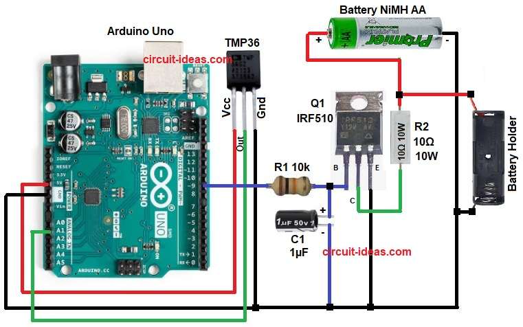
To begin with, Arduino get 5 volt from USB power and then temperature sensor TMP36 give analog voltage to Arduino pin A1, and then Arduino read this value.
If temperature is below safe value then Arduino output goes HIGH to gate of IRF510 and then IRF510 switches ON and allow current to battery through R2 resistor.
After that, capacitor C1 make sensor reading clean and stable.
If temperature go high then Arduino output goes LOW and MOSFET switches OFF and charging stops.
Finally, battery connect to circuit using two wires as shown in circuit diagram: ground of Arduino, battery, sensor MOSFET all are common.
How to Build:
To build a Arduino Battery Charger Circuit follow the below steps for connections:
- First, assemble all the parts as shown in circuit diagram.
- Next, connect Arduino ground to battery ground.
- After that, connect resistor R1 to gate pin of MOSFET
- Then connect R2 between battery positive and MOSFET drain.
- Now connect positive pin of capacitor C1 between R1 resistor and gate pin of MOSFET and negative pin of capacitor C1 connect to GND.
- Also, connect MOSFET source to ground.
- Further, connect sensor TMP36 pins Vcc to 5V, Ground pin to GND, and Vout pin A1 pin of Arduino.
- Connect MOSFET gate to D9 pin.
- Lastly, AA Battery Holder connect one end to Battery positive (+) and AA Battery Holder connect one end to Battery negative (–).
Conclusion:
Overall, this project is about Arduino Battery Charger Circuit and temperature protection make safe charging; also circuit is easy to build and understand.
We can improve this circuit later by adding voltage sensing, current sensing, an LCD display, or solar charging, as this basic design works well for learning and DIY projects.

Leave a Reply