
Nowadays, electronics projects are becoming very popular, especially Arduino based projects are easy to build, because of this the beginners also feel confident.
In this project, an Arduino monitors the sound sensor and triggers the camera flash when it detects a sound.
So Arduino Flash Trigger Circuit with Sound Sensor is very useful for high speed photography for example, balloon burst photography or glass breaking shots.
Therefore, this project is simple and powerful for Camera automation projects and sound based triggering systems.
Arduino Code:
int soundPin = A0;
int flashPin = 7;
int ledPin = 6;
int threshold = 300;

void setup()
{
pinMode(flashPin, OUTPUT);
pinMode(ledPin, OUTPUT);
digitalWrite(flashPin, LOW);
}

void loop()
{
int soundValue = analogRead(soundPin);

if(soundValue > threshold)
{
digitalWrite(ledPin, HIGH);
digitalWrite(flashPin, HIGH);
delay(50);
digitalWrite(flashPin, LOW);
digitalWrite(ledPin, LOW);
delay(200);
}
}
Code Explanation:
- First, the analog pin A0 defined and this pin reads sound sensor output.
- Then flash pin and LED pin, defined.
- After that a threshold value set and this value decides when sound detected.
- In setup function the pin modes, defined.
- Flash pin works as output and LED pin also works as output.
- Initially, flash pin kept LOW.
- In loop function Arduino reads sound value and then it compares with threshold.
- If sound value is higher then flash triggers.
- At the same time the LED glows.
- After a short delay, everything turns OFF.
- So false triggering, reduced.
Circuit Working:
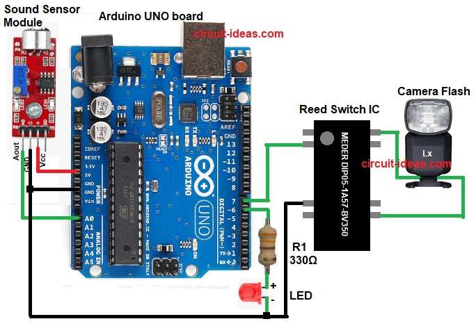
Parts List:
| Components | Values | Quantity |
|---|---|---|
| Resistor | 330Ω 1/4 watt | 1 |
| Arduino UNO | Arduino UNO board | 1 |
| Sound Sensor Module | Microphone based sound detection module | 1 |
| Reed Switch IC | MEDER DIP05-1A57-BV350 | 1 |
| Camera Flash Unit | External camera flash trigger | 1 |
| LED | Red LED | 1 |
First, sound occurs near the sensor and then sound sensor converts sound into voltage.
After that, the Arduino reads the sensor voltage and if the voltage exceeds the preset threshold, the Arduino immediately activates the reed relay, which triggers the camera flash.
At the same time the LED lights up and so the user can see the flash event and then the resistor R1 ensures proper working of the LED and thus the system works very fast.
Formula with Calculation:
Formula for LED Resistor Calculation:
R = (Vsource − Vled) / Iled
where,
- Vsource the supply voltage from Arduino which is 5V
- Vled the forward voltage of the LED which is 2V for red LED.
- Iled the safe current for the LED with 10 mA to 20 mA used.
Vsource is 5V
Vled is 2V
Iled is 10 mA = 0.01 A
R = (5 − 2) / 0.01
= 3 / 0.01
R = 300 ohm
So a 330 ohm resistor used for safety in our circuit.
How to Build:
To build a Arduino Flash Trigger Circuit with Sound Sensor follow the below connection steps:
- Assemble all circuit parts like diagram.
- First, connect sound sensor.
- Then connect sound sensor VCC to Arduino 5V, connect sound sensor GND to Arduino GND and connect sound sensor OUT to Arduino A0 pin.
- Next, connect reed switch.
- After that, connect reed switch pin 1 to Arduino digital pin 7 and connect reed switch pin 6 to ground.
- Then connect LED.
- Now connect Arduino digital pin 6 to R1 330 ohm resistor and connect resistor other end to LED anode and also connect LED cathode to ground.
- Finally, connect flash trigger.
- Connect reed switch output pins to flash trigger input and connect flash ground to Arduino ground.
Conclusion:
Finally, this Arduino Flash Trigger Circuit with Sound Sensor offers a low cost, easy to build project; it also helps beginners understand the basics of sound-triggered flash photography.
The simple wiring makes this circuit easy for beginners to build and it also supports creative photography, and we can improve its performance with a few modifications.
So, this project is a good starting point for happy building and experimenting.