This post talk about how to make small and easy Electronic Organ Circuit using Transistors
It make sound like real organ.
Sound is nice and fun.
We have used transistor and transistor help make sound and give power to speaker.
Circuit is small, but it plays good music.
Good for learning and we can learn how music and electronic work together.
Technology Inside Electronic Organ:
Big organs cost lot money and hard to build but with this small circuit we can make easily at home.
This circuit is simple and there is no need for hard setup.
One part make tone that is the music sound.
Other part is vibrato it make little wave in sound which is more nice to hear.
We can touch probe to pick note we want to play.
Sound changes because of special parts in line.
It does not uses much power so normal battery is enough to run it.
Circuit Working:
Parts List:
| Component Type | Value | Quantity |
|---|---|---|
| Resistors (All resistors are 1/4 watt) | 10k | 1 |
| 4.7k | 1 | |
| 39Ω | 1 | |
| 33k | 2 | |
| 1.8M | 1 | |
| 2k Preset | 1 | |
| 10k Preset | 1 | |
| Capacitors | Electrolytic 50µF 25V | 1 |
| Ceramic 0.1µF | 2 | |
| Ceramic 3000pF | 1 | |
| Ceramic 0.05µF | 3 | |
| Semiconductors | Transistor 2N2926 | 1 |
| UJT 2N2646 | 1 | |
| Switch On Off | 2 |
Important thing probe should not be metal but we can make it any shape.
We can try many types of probe to see which one give nice and clear sound fast.
This circuit uses PP3 battery and take very small current.
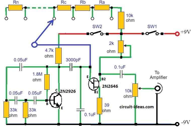
Tone generator are made using unijunction transistor 2N2646, C5, R5, VR1 and tone resistors.
Probe touch the unijunctions emitter to pick right note.
Whole resistance in that line decide what note we hear.
VR1 changes full note range.
Volume control take sound from oscillator through C6 and send to external speaker or amplifier.
This circuit make good sound but maybe not have much feel or charm.
Vibrato unit work between 10 to 30 Hz it only change sound little bit and make it shake soft.
We can build vibrato part separate and join with tone and this give special effect.
It good idea to add this vibrato part.
Oscillator is phase shift type its output connects to unijunctions emitter through C4 from collector.
If probe does not touch the note we wont hear a low sound.
Sometimes phase shift oscillator is little tricky but small change in R3 value can fix problem easily.
Formula:
This formula show how to find music note frequency fnote using total resistance Rtotal:
fnote = 1 / (2 * π * Rtotal * C5)
where:
- Fnote is how fast the note sound the note frequency.
- Rtotal is total resistance in the circuit that affect the note.
- C5 is capacitor value in farads.
- π (pi) is about 3.14159 which is used in many circle and wave math.
Note:
This formula help us find what note will play by using resistance and capacitor values.
It is useful when we build or fix circuit to get right music note or sound.
We can also change values to tune other notes if needed.de possible by adjustments to C5 and Rtotal.
Conclusion:
Making our own electronic organ is fun and great for learning.
It help us understand basics of music and how electronic music tools work.
Now with new techniques and easy parts building electronic organ circuit is more simple than before.
This article talk about how electronic organ works and give idea to learn more.
We can use our imagination and start DIY organ project and make sweet music in our own special way!
Leave a Reply