Power supply is important part of electronic circuits and many analog circuits need positive and negative voltage, for example audio amplifier, operational amplifier circuit and signal processing circuit.
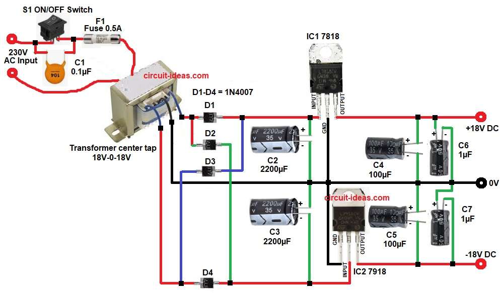
This Dual ±18V Regulated Power Supply Circuit produces +18V and -18V DC output from AC mains, which uses transformer, rectifier diodes, filter capacitors and voltage regulator ICs.
First, AC voltage converts into low AC voltage using transformer, then diodes convert AC to DC and after that capacitors remove ripple voltage and finally regulator IC gives stable output voltage.
Therefore, this circuit provides clean and stable dual power supply.
Circuit Working:
Parts List:
| Components | Values | Quantity |
|---|---|---|
| Capacitors | Ceramic 0.1µF | 1 |
| Electrolytic 2200µF 35V, 100µF 35V, 1µF 50V | 2 each | |
| Semiconductors | Rectifier Diodes 1N4007 | 4 |
| Voltage Regulator IC 7818, IC 7918 | 1 each | |
| Fuse 0.5A | 1 | |
| Transformer center tap secondary 18V-0-18V, primary 230V AC input | 1 | |
| ON/OFF Switch | 1 |
The circuit starts, with AC mains enters the circuit through switch S1 and then the fuse F1 protects the circuit from over current.
Then AC voltage goes to transformer primary and then this transformer reduces the high AC voltage to 18-0-18V AC.
The transformer secondary of the winding has center tap which becomes 0V ground reference.
After that diodes from D1-D4 form rectifier circuit and these diodes convert AC voltage into pulsating DC voltage.
Then capacitors C2 and C3 filter the ripple voltage and they store energy and make smoother DC voltage.
Next, the filtered voltage goes to voltage regulators and the positive regulator IC 7818 produces stable +18V output and the negative regulator IC 7918 produces stable -18V output.
Finally, capacitors C4, C5, C6 and C7 remove remaining noise and improve voltage stability.
Thus, the circuit provides dual regulated output +18V, 0V and -18V.
How to Build:
To build a Dual ±18V Regulated Power Supply Circuit follow the below connection steps:
- Circuit starts, by collecting all the parts as shown in circuit diagram above.
- Then start with transformer primary and connect S1 switch and capacitor C1 in parallel.
- Then connect a fuse from other end of capacitor C1.
- Transformer secondary connect diode D1 anode and cathode of D1 connect to input pin of IC1.
- Connect diode D2 cathode to secondary of transformer and anode of D2 goes to input pin of IC2.
- Connect diode D3 anode to third wire of transformer secondary and cathode of D3 goes to input pin of IC1.
- Connect diode D4 cathode to third wire of transformer secondary and anode goes to input pin of IC2.
- Then start with IC1 7818 pin1 input connect to transformer secondary 18V to cathode of diode D1.
- Pin2 ground connect to circuit ground 0V center tap.
- Pin3 output gives +18V output through capacitors C4 and C7.
- Capacitor C4, C5, C6 and C7 connect between output and ground.
- Capacitor C2 and C3 connects between rectifier diodes and input pin of IC1 and IC2.
- Then start with IC2 7918 Regulator pin1 ground goes to ground of 0V.
- Pin2 is the Input voltage goes transformer secondary to anode of diode D4.
- Finally, pin3 is the output and it goes to -18V output through capacitor C5 and C7.
Conclusion:
This circuit is simple and reliable dual power supply project which produces both positive and negative regulated voltage.
The combination of transformer, rectifier, filter capacitors and regulator IC provides stable output voltage.
Because of regulated output the circuit is useful for sensitive analog electronics which is widely used in audio amplifier and op-amp circuits.
Therefore, this Dual ±18V Regulated Power Supply Circuit is a good choice for many electronic projects.