One tool for checking static electricity is Electroscope Circuit to Measure Electrostatic Charge.
Static electricity happen when object have unbalanced electric charges.
Electroscope help to know if static electricity is there and it is how much.
It just simple conductor.
When something touches it then electroscope charge changes and react.
This movement show what charge was before.
Circuit Working:
Parts List:
| Category | Description | Quantity |
|---|---|---|
| Resistors | ||
| 100k 1/4 watt | 2 | |
| 10k 1/4 watt | 1 | |
| R4 (2 to 20k range) | 1 | |
| Capacitors | ||
| Ceramic C1 (1 to 2μF range) | 1 | |
| Electrolytic 1μF 16V | 1 | |
| Semiconductors | ||
| IC MAX 4322 | 2 | |
| ON/OFF Switch | 1 | |
| Meter 100uA center 0 | 1 |
This DIY electroscope circuit help to find electrostatic charge properly.
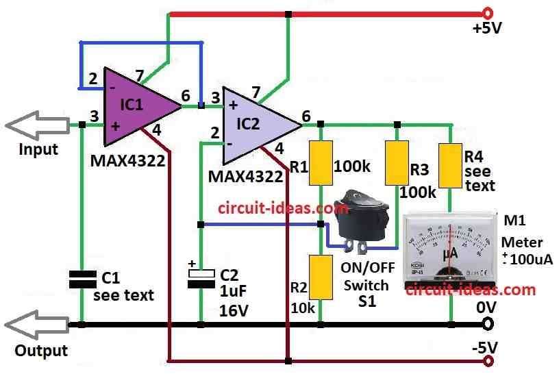
Capacitor C1 is good MKT capacitor and its value is from 1 to 2μF which keep the charge we want to measure.
Formula is U = Q / C1.
It tell how voltage U and charge Q are related in capacitor C1.
This high resistance part is safe because operational amplifier IC2 protect it.
One side of capacitor C1 connect to input wire with test probe.
Other side goes to ground wire this is ground point.
IC2 gives power to meter M1 (±100 μA to ±1 mA center zero) it make low voltage from IC1 stronger.
Switch S1 give two choices for measuring.
When S1 open the gain is 5 and when S1 is closed then gain become 10.
Meter M1 has inside resistance 2.2k ohm.
Resistor R4 from 2 to 20k is not needed if used digital multimeter instead of M1.
This circuit uses MAX 4322 operational amplifiers from Maxim.
These op-amps can work from one rail to other and output can go to power level with normal input voltage.
Formula:
MAX 4322 is good low-noise op-amp made by Maxim Integrated.
It is used for many works where high accuracy and low noise is needed.
Many people use MAX 4322 in amplifier circuits where noise must be low like voltage follower.
To make MAX 4322 detect electrostatic charge we connect it as high impedance buffer to the electroscope sensitive parts.
When using MAX 4322 for measuring electrostatic charge we must remember this is just a simple formula:
Av = Voltage Gain
MAX 4322 can work as unity gain amplifier or voltage follower.
In this setup voltage gain Av is around 1.
Input and Output Resistance:
MAX 4322 is good for high impedance sensors or electrodes because input impedance is very high which is in hundreds of megaohms.
Output impedance is low so we can connect to other stages easily with no problem from loading.
Power Supply Voltage:
Be sure MAX 4322 gets correct power from VCC which is often ±15V but depends on what we do.
Noise Point:
In electroscope circuit where we measure small electrostatic charge or weak signals MAX 4322s low noise is very important.
Formula for voltage follower mode:
Input voltage (Vin) is almost same as output voltage Vout.
Av gain is close to 1.
Important Note:
When used as high impedance buffer MAX 4322 can follow and boost electrostatic charge signals from electroscope sensor.
Because of high input impedance and low noise it work very well for this.
How to Build:
To build a Electroscope Circuit to Measure Electrostatic Charge following steps are required to follow:
Prepare Components:
- First collect all parts we need like in the circuit diagram.
- Check all values of resistors, capacitors and other parts and be sure they are same like in diagram.
Connect IC1 and Capacitor C1:
- One side of capacitor C1 connect to input wire with test probe.
- Other side of C1 goes to ground wire and ground point.
- IC1 work as buffer for high impedance source.
- Connect output of IC1 to input of IC2.
Digital Multimeter:
- If using M1 meter then connect it to circuit which will have 2.2k internal resistance.
- If using digital multimeter instead then there is no need of resistor R4.
Switch S1 with Range of Measurements:
- Switch S1 let us choose two ranges.
- If S1 is closed then gain is 5 and if is open then gain is 10.
Verify Connections Again:
- Check all wires and parts again and ensure they are same like in schematic.
- Turn ON the circuit and use safe electrostatic source to test it.
Modifications:
- Use digital multimeter to adjust and get better reading if needed.
Adjusting:
- Change the circuit a little if needed and check if M1 meter show correct value.
Complete the Circuit:
- After all components are working fine put all parts in proper place and make all connections final.
Conclusion:
This Electroscope Circuit to Measure Electrostatic Charge helps in study of physics and electronics to measure electrostatic charge.
But remember design may change in different circuits.