Anyone wants to know how solar panel work? then go through this article to understand it better.
We can try How to build a Simple Solar Cell Circuit using a 2N3055 Transistor at home which is possible, also, if we like electronics and know transistor then we will enjoy this project.
Furthermore, this model is not big and cannot give more power to house but very good to learn how sunlight turns into electricity.
Circuit Working:
Parts List:
| Category | Item | Quantity |
|---|---|---|
| Semiconductors | Transistor 2N3055 | 1 |
| Voltmeter | 1 |
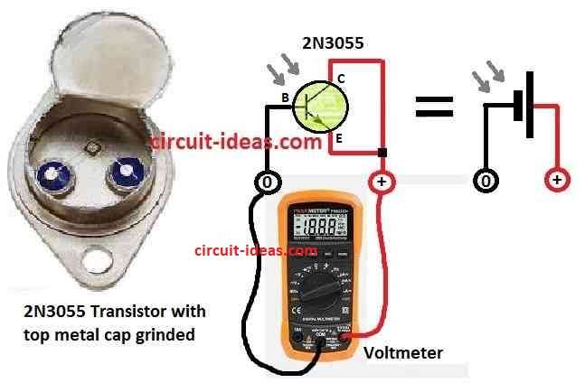
First, take one working 2N3055 power transistor from old extra parts and carefully remove the metal top of the transistor and do it slowly so we do not damage the inside parts.
Look at the above circuit diagram for help.
Now like in circuit diagram connect emitter and collector pin together for positive side and use base pin for negative side.
After that connect and put in sunlight, it makes around 0.7 volt, here 2N3055 transistor is main part for this homemade solar cell.
Also, we can change wire and parts little bit to use it again for catching sunlight.
Here, grinding is important step, so open top and allow sunlight to go inside which will help make voltage between positive and negative pin.
Moreover, this easy trick turn normal transistor into small solar cell, which shows how sunlight can make electricity in simple way.
How to build:
We need to follow these steps to build a simple solar cell circuit using a 2N3055 transistor.
- First, from our electronic parts choose one 2N3055 power transistor and check if it still working.
- Next, use hacksaw to slowly cut and remove metal top of transistor, be careful do not hurt the small parts inside.
- Remember this step is important because sunlight need to go inside the transistor.
- Now connect emitter and collector pins together and this will be positive output and the base pin will be negative output.
- Also, use solder and soldering iron to fix all wires and be sure soldering is clean and wire is not loose.
- Use a multimeter to check if the positive and negative sides give a stable reading and this ensures we connected everything correctly.
- After checking put transistor under strong light or sunlight and be sure the top part is open to the light.
- Lastly, use multimeter again to measure voltage between positive and negative pin, we should see at least 0.7 volts.
Safety:
- Always be careful when using soldering iron and touching electronic parts.
- This 2N3055 solar cell project is just for learning and is not for powering real things.
Note:
- This homemade solar cell does not make big power but it is just for demo, it is small project to help people learn basic idea of how solar energy work.
- This DIY solar cell use 2N3055 power transistor but it not very strong or efficient, also real solar panels are much better and give more power from sunlight.
Conclusion:
To conclude, Solar cell make voltage from sunlight and transistor 2N3055 helps to control and increase output and voltmeter shows how much voltage is coming
This How to Build a Simple Solar Cell Circuit using a 2N3055 Transistor is easy to build and good for learning solar power basics, as it is useful small project for beginners.
Leave a Reply