The IC 741 Based Audible Light Sensor Circuit using LDR is a simple and useful electronic circuit which detects the change in light intensity and gives an audible sound through the speaker.
Also, this circuit works like a light controlled pulse oscillator generator, as IC 741 gives pulse signals at the output and the speaker changes these pulses into sound.
When the light level falls on the LDR, its resistance changes and because of this, the pulse frequency and sound tone also change.
Therefore, this circuit can work as both a light sensor alarm and a pulse tone generator and it is suitable for light detection alarm circuits, beam interruption sensing and simple sound alert systems.
Circuit Working:
Parts List:
| Components | Values | Quantity |
|---|---|---|
| Resistors (All resistors are 1/4 watt) | 1k, 100k, 470Ω | 1 |
| Potentiometer 50k | 1 | |
| LDR (Light Dependent Resistor) | 2 | |
| Capacitors | Ceramic 0.1µF | 1 |
| Electrolytic 4.7µF 25V | 1 | |
| Semiconductors | IC 741 Op-Amp | 1 |
| Speaker 8Ω | 1 | |
| Power Supply 9V DC | 1 |
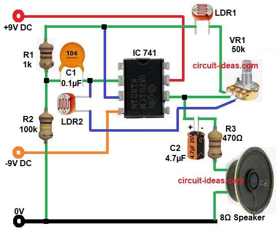
First, the two LDRs sense the surrounding light intensity, where LDR1 works near the upper input side with VR1 resistor and this section helps to adjust the light sensitivity level, by rotating VR1 we can set at what light level the speaker should sound.
Next, LDR2 works at the input section with capacitor C1 and resistor R2 and this part helps the IC receive the voltage signal from the light sensor network.
Then the IC 741 compares the voltage at pin 2 and pin 3, if the voltage at non-inverting input becomes higher than the inverting input, the output at pin 6 goes high and then the output signal passes through capacitor C2 and resistor R3 to the 8 ohm speaker.
Pin 4 of IC goes to -9V so the 741 can work with dual polarity supply and generate better pulse/audio output.
The IC 741 works like a pulse oscillator generator, in other words it gives continuous high and low pulse signals at pin 6.
After that, these pulses pass through capacitor C2 and resistor R3 to the 8 ohm speaker and as a result, the speaker gives an audible tone or pulsing sound.
How to Build:
To build a IC 741 Based Audible Light Sensor Circuit using LDR follow the below connection steps:
- Start, the circuit by collecting all the parts as in diagram above.
- Next, place the IC 741 on the breadboard or PCB.
- Pin 2 of IC connect to capacitor C1 and the LDR2 sensing network.
- Pin 3 connect to the reference network coming from R1 and LDR1 side.
- Pin 4 connect to -9V supply.
- Connect pin 6 to capacitor C2, then connect C2 to resistor R3 and R3 goes to the 8 ohm speaker and ground.
- Pin 7 connect to +9V power supply.
- After that, connect the VR1 upper pin to one end of LDR1, the middle pin goes to pin 6 of the IC and then connect the lower pin to one end of LDR2.
- Next, connect R1 and R2 connect in series between capacitor C1 and ground.
Conclusion:
This IC 741 Based Audible Light Sensor Circuit using LDR is a simple and useful circuit for light detection applications which quickly senses any change in light and gives sound output through the speaker.
Moreover, VR1 lets us adjust the sensitivity very easily and therefore, we can use this circuit for light alarm systems, automatic warning devices and simple object detection projects.
Leave a Reply