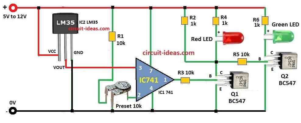
This IC LM35 Temperature Indicator Circuit is small and easy circuit.
It uses LM35 chip to check temperature.
There are no need of many parts and no need of difficult microcontroller.
LED light turn ON when it become too hot or too cold which depend on how we set it.
No need of big computer but just few parts and 5V power like USB charger are needed.
Circuit Diagram:

Parts List:
Type | Component | Quantity |
|---|---|---|
| Resistors | 10k 1/4 W | 3 |
| 1k 1/4 W | 3 | |
| Preset 10k | 1 | |
| Semiconductors | Transistor BC547 | 2 |
| IC 741 | 1 | |
| IC LM35 | 1 | |
| LED Red 20mA 5mm | 1 | |
| LED Green 20mA 5mm | 1 |
How to Build:
To build a IC LM35 Temperature Indicator Circuit follow the below steps:
- First connect IC1 741 op-amp with proper power.
- Then connect IC2 LM35 sensor same like in circuit diagram.
- Join LM35 output to non-inverting pin of op-amp IC1.
- Connect inverting pin of op-amp to one variable resistor and this resistor help to set heat level which is the temperature limit.
- Turn the preset variable resistor to change temperature level as we need.
- Now take output from IC1 and connect to base of Q1 transistor with one resistor R3.
- Then connect collector of Q1 to base of Q2 using resistor R5.
- Put red LED on Q1 collector and green LED on Q2 collector and use 1k resistors for both LEDs.
Working Principle:
- When temperature is low which is below set level then IC1 741 gives no output.
- Then Q1 transistor stay OFF so current connects to base of Q2 through R2 resistor and then green LED will blink.
- But when temperature go high more than set level then IC1 741 give output by turning ON Q1 transistor.
- Now red LED will blink and Q2 transistor will get no current so it will turn OFF.
Formulas:
Here is a easy formula to make LM35 temperature LED circuit better.
LM35 sensor gives voltage that goes same with temperature in Celsius.
The sensor gives output voltage (Vout) like this:
Vout = 10 × T
where:
- Vout is voltage from sensor in millivolt (mV).
- T is temperature in Celsius (°C).
- LM35 give 10 mV for every 1°C.
This means when temperature goes up 1 degree then voltage goes up 10 mV.
This sensor work from around -55°C to +150°C depending on model.
We can also use reverse formula to get temperature from voltage:
T = Vout / 10
LM35 need power supply which is usually 5V.
It give voltage output in line with ground.
This IC LM35 is fast and easy for many temperature check projects..
Conclusion:
This IC LM35 Temperature Indicator Circuit is easy and works good for checking temperature.
No need big or hard microcontroller system.
Using variable resistor in circuit make it flexible.
We can change temperature level easily and this help to use circuit for many different jobs even in factory or industry work.
Leave a Reply