Electronics is very interesting and amplifier circuits are very useful.
One of the basic amplifiers is the common emitter amplifier.
In this circuit an NPN transistor is used which increases small input signal.
An then it gives bigger output signal.
Therefore, this circuit is used in sensors and it is also used in audio and switching circuits.
In short this article explains about a simple Low Cost NPN Transistor Amplifier Circuit.
Circuit Working:
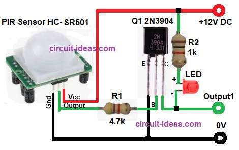
Parts List:
| Components | Value | Quantity |
|---|---|---|
| Resistors | 4.7k, 1k 1/4 watt | 1 each |
| Semiconductors | Transistor 2N3904 NPN | 1 |
| Any color LED | 1 | |
| PIR Sensor HC-SR501 | 1 | |
| Power supply 12V | 1 |
At first, the power supply is applied and then the circuit becomes active.
When input signal is given to the base then base-emitter junction becomes forward biased.
So a small base current flows and because of this the large collector current flows.
As a result, a voltage across collector load changes and thus the output signal is obtained at collector.
When input is high the transistor turns ON and so the LED glows.
When input is low then the transistor turns OFF and so the LED turns OFF.
Hence, the amplification and switching both happen.
Formula with Calculation:
Base Current Formula:
Ib = (Vin – Vbe) / Rb
Calculation as per the circuit:
Ib = (3.3 − 0.7) / 4700
Ib = 2.6 / 4700
Ib = 0.00055 A
Ib = 0.55 mA
So base current is small to about 0.55 mA which is safer for our transistor.
How to Build:
To build a Low Cost NPN Transistor Amplifier Circuit follow the below steps for connection:
- First, collect all components.
- See the circuit diagram clearly and then start the work.
- Emitter pin of transistor Q1 go to ground.
- Base pin of Q1 connect to sensor OUT pin.
- Put resistor R1 in between.
- Collector pin of Q1 connect to LED cathode.
- LED anode connect to one end of resistor R2.
- Other end of resistor R2 go to +12V supply.
- Now connect PIR sensor pins.
- V+ pin go to +12V.
- V- pin go to ground.
- Sensor OUT pin go to base resistor R1.
- Now circuit making is finished.
Conclusion:
To conclude, this Low Cost NPN Transistor Amplifier Circuit is very useful.
It is simple and effective and it amplifies small signals easily.
Also, it can work as a switch.
Therefore, this circuit is best for beginners and it is widely used in electronics projects.
References:
Creating a 3.3 V audio amplifier using an NPN 2N2222 transistor
Leave a Reply