
Battery power plays an important role in electronic circuits, but the battery voltage can drop without warning; as a result, devices may stop working suddenly, making a low-voltage alarm necessary.
This Low Voltage Alert Circuit for 9V Battery gives warning when a 9V battery goes low, as it uses LM339 comparator IC and also uses few simple available components which can be build easily.
Furthermore, the circuit offers a low-cost and reliable design, making it suitable for beginners and hobby projects.
Circuit Working:
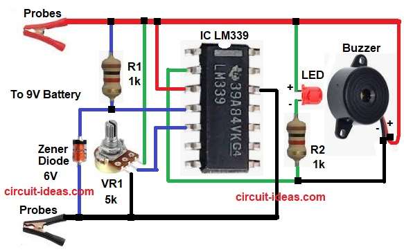
Parts List:
| Components | Values | Quantity |
|---|---|---|
| Resistors | 1k | 2 |
| Potentiometer 5k | 1 | |
| Semiconductors | IC LM339 Comparator | 1 |
| LED any color | 1 | |
| Zener Diode 6V | 1 | |
| Buzzer 5V to 9V DC | 1 | |
| Probes / Clips for battery terminals | 2 | |
| Battery 9V | 1 |
First, connect the 9 V battery to the circuit, then the Zener diode generates a fixed 6 V reference voltage and applies it to the non-inverting input of the LM339.
Meanwhile, VR1 and R1 divide the battery voltage and apply the divided voltage to the inverting input of the LM339.
Now, when battery voltage is normal the inverting input voltage is higher than reference voltage and therefore, output of LM339 remains LOW and as a result a LED and buzzer remain OFF.
However, when battery voltage drops the divided voltage also drops and after that, it becomes lower than reference voltage and therefore, LM339 output becomes HIGH.
Now the LED glows and the buzzer sounds, clearly indicating a low battery condition.
Formula with Calculation:
Reference voltage from Zener diode Vz is 6V
Voltage divider formula:
Vout = Vin × VR1 / (VR1 + R1)
As per circuit the battery voltage:
- Vin is 9V
- VR1 is 5k
- R1 is 1k
Vout = 9 × 5 / (5 + 1)
Vout = 9 × 5 / 6
Vout = 7.5V
When battery voltage reduces to around 7V the divider voltage becomes less than 6V reference, so, comparator switches output.
How to Build:
To build a Low Voltage Alert Circuit for 9V Battery follow the below connection steps:
- First, start collecting all the parts as shown in circuit diagram.
- Next, pin 2 of IC the output pin and connected to LED, resistor R2.
- Then pin 3 of IC the Vcc pin connected to positive supply.
- Now pin 4 of IC the -input1 pin connected to positive supply through resistor R1.
- Further, pin 5 of IC the +input1 pin connected to center pin of VR1 pot.
- After that, pin 12 of IC the GND pin connected to negative supply of battery.
- Further, Zener diode cathode connected from pin 4 of IC and anode connected to negative of battery.
- Also, two probes connected to 9V battery source.
- Finally, buzzer one end connected to positive supply and other end connected to junction R2 and pin 2 of IC.
Conclusion:
To conclude, this Low Voltage Alert Circuit for 9V Battery is very simple and it is easy to make and easy to test as it uses very few components; so, beginners can try this circuit easily.
LM339 IC gives stable voltage comparison and therefore, alarm works properly every time and thus, this circuit helps to protect battery powered devices.