Batteries play an important role in many electronic systems; however, their voltage drops over time, and if it falls too low, the battery may become damaged.
So low voltage indication needed.
Therefore, this 12 V Battery Low Voltage Alarm Circuit protects the battery by providing visual and audible alerts; also its simple, low-cost design uses readily available components.
In this circuit, the LM339 comparator IC compares the battery voltage with a reference voltage and when the battery voltage falls below the reference voltage, the LED and buzzer turn ON.
Circuit Working:
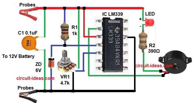
Parts List:
| Components | Values | Quantity |
|---|---|---|
| Resistors | 1k, 390Ω | 1 each |
| Potentiometer 4.7k | 1 | |
| Capacitor | Ceramic 0.1uF | 1 |
| Semiconductors | IC LM339 Comparator | 1 |
| LED any color | 1 | |
| Zener diode 6V 1N5233 | 1 | |
| Buzzer 5V to 9V | 1 | |
| Probes / Clips for battery terminals | 2 | |
| 12V 45Ah Lead-acid battery | 1 |
To begin with, the circuit operates from a 12V DC battery; the LM339 is a quad comparator IC, but this circuit uses only one of its comparators.
First, connect the battery to the input clips, the resistor network then divides the battery voltage and applies the divided voltage to the comparator input.
Meanwhile, Zener diode ZD1 provides a fixed 6 V reference voltage and applies it to the comparator input, then VR1 fine-tunes the reference level.
Now comparator compares both voltages and when battery voltage is higher than set level then output remains OFF and so LED and buzzer stay OFF.
However, when battery voltage falls below preset value then comparator changes output state and then LED glows immediately and at the same time buzzer starts sounding.
Thus, the user receives a clear warning and can recharge the battery in time.
How to Build:
To build a 12V Battery Low Voltage Alarm Circuit follow the below connection steps:
- First, start gathering all the parts as shown in circuit diagram.
- Next, pin 2 of IC the output pin and connected to Buzzer ,R2 and LED.
- Then pin 3 of IC the Vcc pin and connected to positive supply.
- After that, pin 4 of IC the -input1 pin and connected to positive supply through resistor R1.
- Now pin 5 of IC the +input1 pin and connected to center pin of VR1 pot.
- Also, pin 12 of IC the GND pin and connected to negative supply of battery.
- Further, Zener diode cathode connected from pin 4 of IC and anode connected to negative of battery.
- Then two probes connected to 12V battery source and finally, capacitor C1 connected from positive supply to GND
Conclusion:
Overall, this 12V Battery Low Voltage Alarm Circuit is very useful, as it prevents deep discharge of battery and also it gives timely warning; also the circuit is simple and reliable which anyone can build it easily.
Therefore, this circuit is best for battery protection projects.

Leave a Reply