This project show about Magnetic Field Detector Circuit using Hall Sensor And Arduino.
When magnet come near sensor, the buzzer beep and LED glow.
Arduino read sensor output and give alarm when magnet is present.
This project is simple and good for beginners.
Arduino Coding:
void setup() {
pinMode(8, INPUT);
pinMode(7, OUTPUT);
pinMode(6, OUTPUT);
}

void loop() {
int sensor = digitalRead(8);

if (sensor == 0) {
digitalWrite(7, HIGH);
digitalWrite(6, HIGH);
} else {
digitalWrite(7, LOW);
digitalWrite(6, LOW);
}
}
Code Explanation:
- pinMode set pin type.
- Sensor pin is INPUT because Arduino read it.
- LED and buzzer pins are OUTPUT because Arduino control them.
- digitalRead read value from Hall sensor.
- If sensor read 0 then magnet is near.
- Then Arduino turn LED ON and buzzer ON.
- If sensor read 1 then there is no magnet.
- Then Arduino turn OFF LED and buzzer.
Circuit Working:
Parts List:
| Part Name | Quantity |
|---|---|
| Resistor | |
| 220Ω 1/4 watt | 1 |
| Semiconductors | |
| Arduino UNO | 1 |
| KY-024 Hall Effect Sensor | 1 |
| Buzzer | 1 |
| LED any 5mm | 1 |
| USB Cable | 1 |
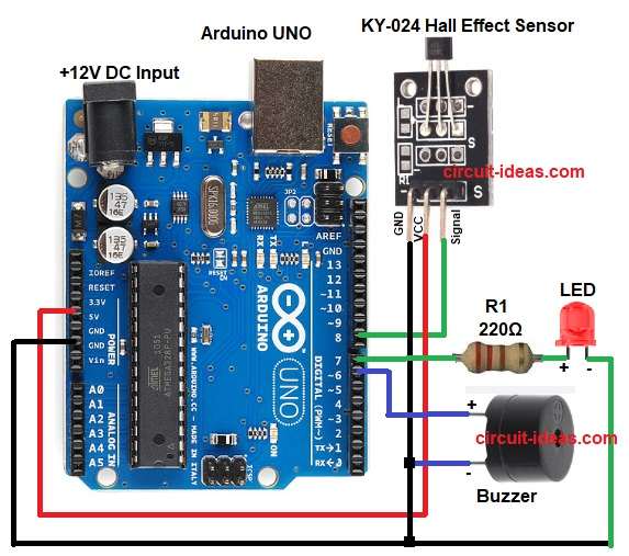
The above circuit diagram uses a buzzer and LED that turn ON when the sensor detects any weak or strong magnetic field.
Hall effect sensor give digital signal.
When magnet is close, sensor output go low or high depending on module type.
Arduino read this output pin.
If Arduino see magnet then it turn LED ON and turn buzzer ON.
If magnet is not present then Arduino keep them OFF.
Formulas with Calculation:
LED resistor calculation:
Arduino voltage = 5V
LED forward voltage approx = 2V
LED current needed = 10mA
Resistor = (5 – 2) / 0.01 = 300 ohm
Nearest standard is 220 ohm
So in this circuit we used 220 ohm resistor.
How to Build:
To build a Magnetic Field Detector Circuit using Hall Sensor And Arduino follow the below steps for connection:
- Take all the parts as shown in circuit diagram.
- Hall sensor Signal pin goes to Arduino digital pin 8.
- Middle pin goes VCC to Arduino 5V.
- GND pin goes Ground to Arduino GND.
- LED long leg is connected to Arduino pin 7 through 220 ohm resistor.
- LED short leg goes to GND.
- Buzzer positive pin goes to Arduino pin 6.
- Buzzer negative pin goes to GND.
Conclusion:
This Magnetic Field Detector Circuit using Hall Sensor And Arduino is simple and easy to make.
The system detect magnet fast and give sound and light alert.
Good for learning sensor reading, digital pins and simple alarms.
We can use it in door alarms, magnetic switches and robot sensing.