Practical Emergency Tube Light Circuit gives light when power goes OFF, as this project uses few parts to make emergency light work well.
Circuits min parts are step-down transformer, pulse switch circuit and tube light, in addition, this tutorial teaches us how the circuit works and how to build it.
Circuit Working:
Parts List:
| Components | Values | Quantity |
|---|---|---|
| Resistors | 680Ω 3W | 1 |
| Preset 2k | 1 | |
| Capacitor | PPC 0.47µF 400V | 1 |
| Semiconductors | Transistor TIP3055 | 1 |
| Step-Down Transformer 12-0-12V 1AH | 1 | |
| Battery 12V 7AH | 1 | |
| Fluorescent Tube Light 20W | 1 |
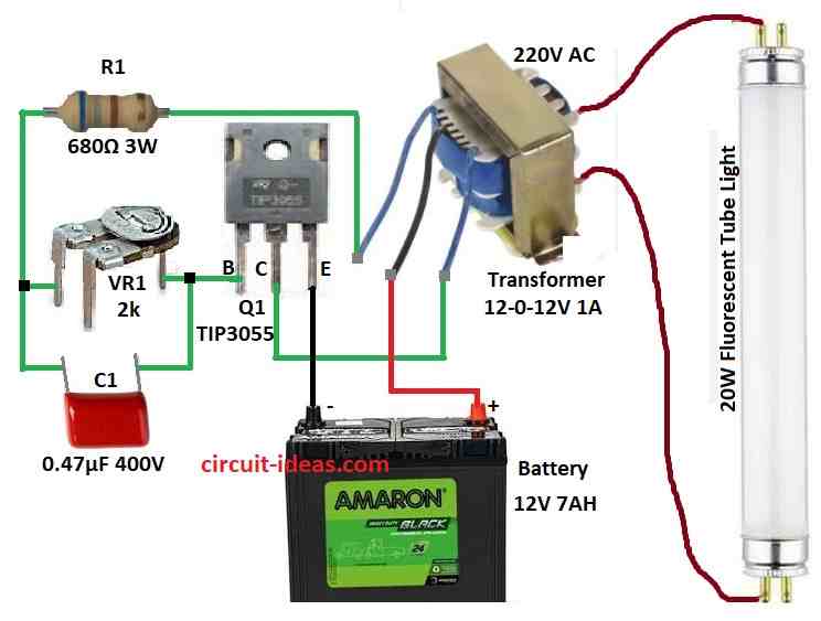
To begin with, this circuit uses 12-0-12V step-down transformer to run fluorescent light, its primary side connect to 20W tube light and secondary center tap goes to pulse switch circuit.
How it works:
First, capacitor C1 and variable resistor VR1 form a pulse generator and together they control the timing and speed of the pulses, then, these pulses go to the base of the power transistor Q1 (TIP3055).
Then Q1 act like switch and connects and disconnect battery to transformer fast and then this make EMF (electromagnetic force) in transformer.
After that, EMF increase voltage in primary side which is enough to light 20W tube.
Formulas and Calculations:
Here, are the formulas and simple calculations for emergency tube light circuit:
Formula:
f = 1 / (2 * π * R * C)
where:
- f is the frequency in Hz
- R is the resistance in ohms
- C is the capacitance in farads
Given:
R = 2k ohms and C = 0.47µF = 0.47 × 10⁻⁶ F
f = 1 / (2 × 3.1416 × 2000 × 0.47 × 10⁻⁶)
f = 169.6 Hz
Hence, Oscillation Frequency is 169.6 Hz .
How to Build:
To build a Practical Emergency Tube Light Circuit follow the below mentioned connections steps:
- First, collect all parts shown in the circuit diagram.
- Next, connect base of TIP3055 transistor to one end of variable resistor VR1, connect other end of VR1 to one end of resistor R1 and connect other end of R1 to one wire of transformer check the circuit diagram.
- After that, connect collector of TIP3055 to same wire of transformer and then connect emitter of TIP3055 to negative (-) of 12V battery.
- Now connect capacitor C1 across both ends of VR1.
- Then connect center tap wire of transformer to positive (+) of 12V battery and finally, connect 20W tube light to secondary 220V side of transformer.
Conclusion:
To conclude, this Practical Emergency Tube Light Circuit is cheap and useful, as it uses basic parts like transformer, VR, capacitor and transistor.
Moreover, it can power 20W tube light when power goes OFF, furthermore, this circuit is also good for DIY and works well in blackout.