Think this circuit is like a smart switch for our home things which wait for some time before power comes.
This Simple 220V Time Delay Switch Circuit with Triac work like power button but it does not gives power fast. It waits for little time and then gives power to light, fan or motor.
We can choose how long it can wait for some seconds or maybe for some minutes.
Inside, it uses special part named as triac which is for controlling power.
We can use this for heater so there is not much load for the same time or for stage light which makes small wait before light is ON which looks nice.
Circuit Working:
Parts List:
| Category | Component | Quantity |
|---|---|---|
| Resistors | 22k 1/4 watt | 1 |
| 1k 1/4 watt | 1 | |
| 220Ω 1/4 watt | 1 | |
| Capacitors | Electrolytic 1000µF 50V | 1 |
| Electrolytic 470µF 50V | 1 | |
| Electrolytic 100µF 50V | 1 | |
| Semiconductors | SCR BT169 | 1 |
| Triac BT136 | 1 | |
| Diode 1N4007 | 1 |
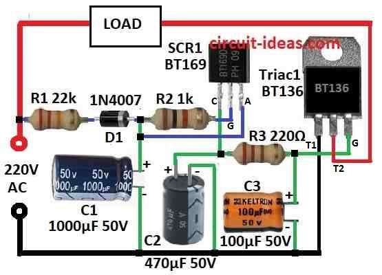
This circuit is for time delay switch which turns ON AC load like lamp after 3 minute delay.
It help protect load from big current rush and power spikes that can hurt the device.
Switch connect direct to AC power to work.
Resistor R1 drop the AC voltage and diode D1 change it to low DC voltage.
Big capacitor C1 do two things it smooth the DC and also makes the delay time.
The SCR start work only after C1 is fully charge which takes near 2 minutes.
When C1 is full SCR get small signal at gate and it start to conduct.
Then C2 start charging this gives 1 more minute delay to make Triac turn ON using R3.
When Triac turns ON AC power connects to load and device start working.
Capacitor C3 keep voltage stable at Triac gate and stops any flicker or problem.
Be very careful as this circuit use high voltage from mains which can kill.
Do not touch anything when power is ON.
Only expert person should build this circuit.
Formula:
RC timing circuit uses resistor and capacitor to make time delay for SCR circuit.
The resistor R and capacitor C decide how long delay happen.
This is simple formula to find time delay in RC circuit:
t = R × C × 1.1
where:
- t is delay time in seconds R is resistor value in ohms Ω
- C is capacitor value in farads F
Important things:
The 1.1 in formula help give correct timing it fixes delay and SCR trigger time.
Choose resistor and capacitor with right voltage and power rating for the circuit.
Sometimes real parts are not the same as number written on them so test circuit to check real delay.
With this formula we can make time delay using SCR, resistor and capacitor.
If the circuit need different delay we can change R or C values to adjust it.
How to Build:
Below are the steps for building a Simple 220V Time Delay Switch Circuit with Triac:
Safety First:
- Be sure we work in safe place and all parts must be unplugged before we begin.
Circuit Design:
- Look at the circuit diagram before we start.
Put Components:
- Put all parts on breadboard or PCB same like in diagram.
- Leave space between parts so no short circuit happen.
Power Connection:
Test Circuit:
- After building test the circuit by giving power.
- Triac should turn ON after some time delay.
- Time delay depends on R1, R2 and C1.
- Change these if delay is not right.
Connect Load:
- If circuit works good then connect AC load like lamp to Triac output.
Final Check:
- Check all wires again and be sure everything is tight and covered.
How It Works:
- Turn ON the power and see how long it takes to turn ON the load.
- If delay is not perfect then adjust parts again.
Important Safety Warning:
- This circuit uses 220V AC and is very dangerous!
- Always be very careful and follow safety rules.
- All parts must be covered and strongly connected.
- If anyone do not know how to work with high voltage them ask someone who knows it better Or talk to real electrician.
Conclusion:
We can make Simple 220V Time Delay Switch Circuit with Triac using normal electronic parts.
This circuit waits for some time before turning ON AC load like lamp after power come.
Be very careful when making and testing this circuit because it uses high voltage.
Leave a Reply