Simple 555 Timer Based Animal Repeller Circuit is small device to keep animals away.
It make high sound which animals do not like and humans mostly do not hear it.
Main part is IC 555 timer which make high frequency sound.
Sound is around 15 kHz to 120 kHz (ultrasonic).
This circuit is easy to build, work with 9V battery and is good for home use.
Circuit Working:
Parts List:
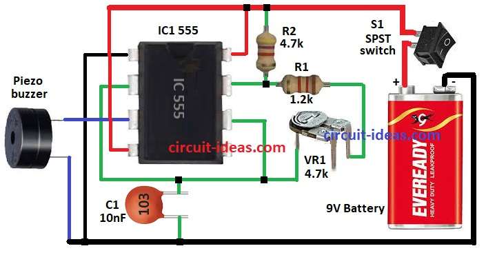
| Component | Specification | Quantity |
|---|---|---|
| Resistors | 1.2k, 4.7k 1/4 watts | 1 each |
| Preset 4.7k | 1 | |
| Capacitor | Ceramic 10nF | 1 |
| Semiconductors | IC 555 | 1 |
| Piezo Buzzer 82dB | 1 | |
| Switch SPST | 1 | |
| Battery 9V | 1 |
Circuit uses 555 timer IC in astable mode.
Frequency depends on resistors R1, VR1 preset, R2 and capacitor C1.
555 IC give output to piezo buzzer.
Buzzer make ultrasonic sound when get power.
We can change sound frequency by turning VR1.
Animals hear high frequency well and this sound bother them so they go away.
Important:
This device does not hurt animals but it just make sound they do not like.
Keep it 1 meter 3 feet away from home pets sleep or food place or it may stress them.
Formulas with Calculations:
Below are formula and calculations for 555 Timer Animal Repeller Circuit:
Frequency of 555 in astable mode:
f = 1.44 / [(R1 + 2VR1) × C1]
where:
- f is the frequency in Hz
- R1 is the 1.2kΩ for fixed resistor
- VR1 is the 4.7kΩ for variable resistor
- C1 is the 10nF capacitor
When VR1 = 0Ω:
R total = 1.2kΩ
f_max = 1.44 / (1.2k × 10nF) = 120 kHz
When VR1 = 4.7kΩ:
R total = 1.2k + 2×4.7k = 10.6kΩ
f_min = 1.44 / (10.6k × 10nF) = 13.6 kHz
So frequency can change from 13.6 kHz to 120 kHz.
How to Build:
To build a Simple 555 Timer Based Animal Repeller Circuit follow the below mentioned steps:
- Collect all parts from circuit diagram.
- Pin 1 of IC1 goes to GND.
- Connect pin 2 and pin 6 together.
- Put C1 from pin 2.
- Pin 3 go to one side of piezo buzzer and other side of buzzer goes to GND.
- Connect R1 and VR1 between pin 2 and pin 7.
- Connect R3 from pin 7 to positive supply.
- Pin 4 and pin 8 go to positive supply.
- Use SPST switch from positive supply to +9V battery and battery negative go to GND.
Conclusion:
This Simple 555 Timer Based Animal Repeller Circuit make ultrasonic sound because which animals do not like it.
It uses 555 timer in astable mode.
Circuit is small, low cost, work with 9V battery and is easy to carry and use.
Leave a Reply