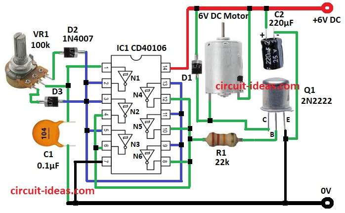
This 6V DC Motor Speed Controller Circuit using IC CD 40106 controls 6V DC motor speed.
Change speed by change in duty cycle of input voltage.
Circuit is cheap, easy, good for toy motor, small fan and blower.
Main part of this circuit is IC CD 40106 Schmitt trigger inverter which makes PWM signal.
PWM controls motor speed through transistor switch which is smooth and with fast adjust.
Circuit Working:
Parts List:
| Component | Specification | Quantity |
|---|---|---|
| Resistors | 22k 1/4 watt | 1 |
| Potentiometer 100k | 1 | |
| Capacitors | Ceramic 0.1µF | 1 |
| Electrolytic 220µF 25V | 1 | |
| Semiconductors | IC CD 40106 | 1 |
| Transistor 2N2222 | 1 | |
| Diodes 1N4007 | 3 | |
| 6V DC Motor | 1 |
Circuit work by PWM (Pulse Width Modulation).
PWM control average voltage to motor by change duty cycle of square wave.
IC CD 40106 Schmitt trigger NOT gate make PWM.
N1 work as PWM oscillator and PWM from N1 goes to N2 to N6 inputs and outputs join and goes to base of Q1 2N2222 via R1.
C1 + VR1 set timing.
D2 and D3 change charge and discharge time which changes duty cycle.
Turn VR1 to change duty cycle.
Q1 boost signal and act as switch for 6V motor.
D1 1N4007 protect from back EMF.
This circuit work on 6V DC and is good for low power projects.
Formulas with Calculations:
PWM Frequency:
Formula: f = 1 / (0.693 × (R_charge + R_discharge) × C)
Example:
where,
- C = 0.1µF, R_charge = 50kΩ, R_discharge = 50kΩ
f = 1 / (0.693 × (50k + 50k) × 0.1µF) = 144 Hz
Duty Cycle:
Formula: D = (R_charge / (R_charge + R_discharge)) × 100%
Example:
where,
- R_charge = 70kΩ, R_discharge = 30kΩ
D = (70k / (70k + 30k)) × 100% = 70%
Motor get power 70% of time in each cycle.
How to Build:
To build a 6V DC Motor Speed Controller Circuit using IC CD 40106 following steps are required to be followed while connections:
- Gather all the parts as shown in circuit diagram
- Connect pin 1 of IC1 N1 to center pin of VR1
- Connect top leg of VR1 to pin 2 of IC1(N1 through diode D2
- Connect bottom leg of VR1 to pin 2 of IC1 N1 through diode D3
- Connect pin 3 of IC1 N2 to pin 2 of IC1 N1
- Connect all inputs of N2, N3, N4, N5, N6 together
- Connect all outputs of N2, N3, N4, N5, N6 together
- Connect capacitor C1 from pin 1 of IC1 N1 to GND
- Connect common outputs of N2 to N6 to base of Q1 through resistor R1
- Connect collector of Q1 to one lead of 6V DC motor
- Connect other lead of motor to 6V positive supply
- Connect anode of diode D1 to collector of Q1 and cathode of D1 to 6V positive supply
- Connect emitter of Q1 to GND
- Connect positive of capacitor C2 to 6V positive supply and negative of C2 to GND
Conclusion:
This 6V DC Motor Speed Controller Circuit using IC CD 40106 is cheap and easy design to make.
It uses CD 40106, VR1 and transistor switch.
Circuit is smooth, accurate for speed change.
It is good for small DC motors, hobby, robot and automation.