This smart design for 9V to 300V Converter Circuit changes a small 9V battery power into big 300V power.
It uses only one transistor and is very simple and easy for one to try.
This circuit is good for learning and for small projects.
What is a 9V to 300V Converter:
A circuit called as 9V to 300V converter change from small 9V power to big 300V power.
This type of circuit is part of DC-to-DC converter family.
It uses different parts and simple design to do its job.
Circuit Working:
Parts List:
| Category | Description | Quantity |
|---|---|---|
| Resistors | 1/4 W CFR | |
| 100k | 1 | |
| Capacitors | ||
| Ceramic 0.01µF, 0.1µF | 2 | |
| PPC 0.47µF 400V | 1 | |
| Electrolytic 100µF 25V | 1 | |
| Semiconductors | ||
| Transistor 2N2222 | 1 | |
| Diode 1N4007 | 1 | |
| Transformer 9-0-9V 1Amp 250V | 1 |
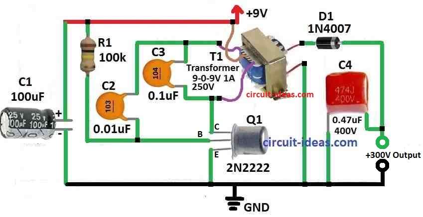
Using single transistor circuit shown above, we can see how 9V to 300V converter work:
To make 9V into around 250V we need part T1 transistor.
T1s main winding is do this change.
This winding also work like coil inductance L for Hartley oscillator.
Hartley oscillator is simple circuit with coil and capacitor that make AC signal.
T1s second winding make voltage go higher.
Here 9V become around 350V.
Diode D1 do half wave rectification after voltage become high.
It let only one side of AC signal pass so current flow in one direction.
Capacitor C4 take this current and get charged.
C4 also smooths out the signal to make it more stable DC voltage.
It store energy and gives output around 300V.
Even with small load voltage stays around 300V.
Be careful with C4 capacitor.
If there is no load it can keep charge and give small shock if we touch.
Shock are not deadly but can be strong and surprise people.
So this circuit uses transformer, oscillator, diode and capacitor to change 9V into high DC voltage.
Always handle with care because of stored charge in capacitor C4.
Formulas and Calculations:
To make simple high voltage power supply circuit we can build DC-DC converter with one transistor.
It takes 9V input and make around 300V output.
Below is easy formula to help make this circuit using needed parts:
How to Find Oscillator Frequency:
The resistor and capacitor connected to transistor base and decide how fast oscillator works.
If we use 2N2222 transistor we can use this basic formula:
f = 1 / (R × C × 1.1)
where:
- C is the capacitor in oscillator like 0.01µF
- R is the resistor like 100k ohm
So if we use 0.01µF and 100k:
f = 1 / (100,000 × 0.01 × 1.1) = about 90 kHz
This simple setup show how voltage can go up in easy way for learning.
But in actual circuit use we need better design with feedback and more parts to keep voltage stable and safe.
How to Build:
To build a 9V to 300V Converter Circuit below steps should be followed for connection:
Transformer T1:
- Connect 9-0-9 volt power to main winding of T1.
- T1s second winding make big voltage.
Inductor L:
- Use main winding of T1 as inductor L in circuit.
- Then connect it to other parts of circuit.
- Use transistor, resistors and capacitors to build oscillator.
- Which transistor and part values to use depend on design.
- Check circuit diagram to connect parts correct.
Secondary Winding of T1:
- Connect oscillator to T1s second winding.
- This help to step up voltage higher.
Diode D1:
- Add diode D1 after T1 to fix AC signal.
- Diode let only one side of waveform go through.
Capacitor C4:
- Connect C4 after diode.
- It smooths out the voltage and make DC more stable.
Output Load:
- Connect load resistor or other device to output side.
- This show how converter work in actual use.
Power Supply:
- Give power to circuit using 9V battery.
Testing the Circuit:
- Turn ON circuit and watch output voltage.
- If voltage is not correct try to change part values.
- Be careful with C4 capacitor, it can keep charge and give shock.
- Use safety steps like discharge resistor to stay safe.
Conclusion:
This guide show how to make 9V to 300V Converter Circuit using only one transistor.
We can change parts based on what we have and our needs.
Always follow safety rules when working with high voltage.
Leave a Reply