This Adjustable Power Supply Circuit using IC TDA2030 can change the voltage it uses small trick which is little bit surprising.
The chip TDA2030 is normally for making speaker sound loud and can also work like voltage controller.
With smart circuit design it gives steady DC voltage.
We can change output which is good for many electronic projects with different voltage need.
But this is not normal way to use TDA2030 but there are other circuits which are better for adjustable power supply.
Circuit Working:
Parts List:
| Category | Component | Quantity |
|---|---|---|
| Resistors | Potentiometer 25k 1/4 watt | 1 |
| Preset 25k | 1 | |
| Capacitors | Ceramic 100nF | 3 |
| Electrolytic 100µF 63V | 1 | |
| Semiconductors | IC TDA2030 | 1 |
| IC 78L05 | 1 |
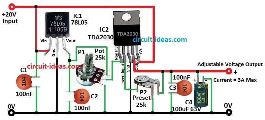
This circuit uses a normal 78L05 and audio amplifier chip TDA2030 to make easy adjustable voltage regulator.
Output voltage can go up to 20V and max current is 3A.
TDA2030 have good protection for heat and short circuit so circuit last a long time.
Circuit is very simple and we can see in schematic.
Only there is need of two ICs, one potentiometer, one preset and some small capacitors.
To set voltage first turn P1 to max side where wiper connects to 78L05 and then change P2 small trimpot until we get output voltage we want.
After that use P1 to move voltage up and down between almost 0 and max.
If output current is low then there is no need for special cooling.
But if current goes over 1A or input and output voltage which is very different then TDA2030 gets hot and need small heatsink to cool down.
How to Build:
To build a Adjustable Power Supply Circuit using IC TDA2030 below are the steps mentioned:-
Mount Components:
- Put 78L05, TDA2030, variable resistors and capacitors on breadboard or PCB like in the circuit diagram.
Connect Components:
- Connect 78L05 input to power supply.
- Connect 78L05 output to TDA2030 input using potentiometer.
- Connect TDA2030 output to the load.
- Check all parts have same ground.
Adjustment Potentiometers:
- Turn potentiometer P1 to max side.
- Then turn the preset P2 until we get the max voltage we want.
- Turn ON the power and then use multimeter to check voltage output.
- Turn P1 to change voltage from almost 0 to max.
Finalize and Secure:
- If everything is working good then fix all wires and parts and make it strong and safe.
Testing and Optimization:
- Try different loads to see if circuit stay stable and change little things if needed.
Note:
- Be careful with electronic parts, they can be dangerous.
- High voltage can hurt.
- Always work safe there should be no power when changing wires.
- If we are not sure what to do then ask someone who know electronics better.
Conclusion:
This Adjustable Power Supply Circuit using IC TDA2030 is useful and works good for many electronic projects.
TDA2030 can work like voltage regulator and amplifier.
With some other parts like bridge rectifier, capacitors and variable resistors it gives stable and changeable output voltage.
But be careful when current is high TDA2030 can get hot as it needs good cooling to keep it working nice and safe.