This Automatic Power Delay OFF Circuit is like small helper to remind us to turn OFF things.
We can connect it with our device with the time frame like 1 hour, 2 hour as it stops the power by itself.
It is very useful if we want to keep nightlight ON for some time or fan turn OFF after we sleep.
Circuit Working:
Parts List:
| Type | Value | Quantity |
|---|---|---|
| Resistors | 10k 0.5W | 2 |
| 1M 0.5W | 1 | |
| 470Ω 1/4 watt | 1 | |
| Capacitors | Ceramic 0.01µF | 1 |
| Electrolytic 220µF 25V | 1 | |
| Electrolytic 1000µF 16V | 1 | |
| Semiconductors | IC 555 | 1 |
| Triac BT136 | 1 | |
| Zener diode 1W 8.2V | 1 | |
| Diode 1N4007 | 1 | |
| Push button | 1 | |
| 3 Pin socket | 1 | |
| Fuse 1A | 1 |
This circuit use 555 IC and it turn OFF power by itself after 20 minutes.
We can use it like for turn OFF the outside light after we lock the house.
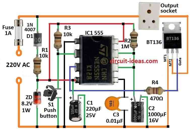
The 555 IC work like monostable when we press S1 for short time the output goes high and triac turn ON and gives power to socket.
After that IC output goes low when C2 get charged up to 2/3 of power voltage and this take near 20 minutes.
C2 must be a of good quality with low leak and If it is not then it will charge slow or maybe will not charge full.
Timer get power from half wave rectifier D1, dropping resistor R1, Zener D2 and filter capacitor C1.
Formulas:
Best timer to make time delay is 555 IC in monostable mode.
In this mode it have only one stable state.
After it get trigger it goes to temporary state for some time and then come back to stable again.
Formula for 555 Monostable Timer (Auto Power Delay OFF):
To find time delay T in seconds:
T = 1.1 × R1 × C1
where:
- T is time delay in seconds
- R1 is resistor in ohms
- C1 is capacitor in farads
Extra Information:
We can put trimmer capacitor with C1 to adjust timing better.
If we want longer delay use transistor or more 555 stages, because R1 and C1 have some limit.
Be sure power voltage for 555 IC stay in correct range always.
How to Build:
To build a Automatic Power Delay OFF Circuit follow the below mentioned steps for connections:
- Connect pin 2 of 555 IC to one side of push button switch S1.
- Other side of S1 will connect to ground.
- Pin 4 and pin 8 connects to positive supply +Vcc.
- Pin 1 of 555 IC connects to ground.
- Pin 5 connect to ground using capacitor C3.
- Pin 6 and pin 7 join together.
- Then connect to one side of resistor R2 and also to one side of capacitor C2.
- Other side of C2 will connect to ground.
- Pin 3 connects to gate of triac BT136 through resistor R4.
- Anode of diode D1 connects to power supply +Vcc and the cathode connects to where resistor R1 connects.
- Cathode of Zener diode connect to same point as R1 and anode connects to ground.
Note:
- Be sure capacitor C2 is of good quality and with low leakage.
- It must be correct size to get near 20 minutes delay.
- If delay is not correct then change values of R1 and C2 to adjust timing.
Conclusion:
An Automatic Power Delay OFF Circuit is helpful circuit it turn OFF the power to device by itself after some time.
People use it in many places to save energy, control device working and make system work better.
This circuit is easy and good way to control power automatic in many different situations.
References:
What is a Delay Circuit? 6 Types of Delay Circuits Explained