Simple Boost Converter LED Torch Circuit using IC MAX660 is small but useful light tool.
This project use MAX660 chip to make LED torch work well.
MAX660 boost 3V battery to higher voltage and can light many LEDs.
It is good for battery devices needing more voltage and with no inductor needed.
Circuit design also makes battery last longer.
Circuit Working:
Parts List:
| Component | Specification | Quantity |
|---|---|---|
| Capacitors | ||
| Electrolytic 100µF 10V | 1 | |
| Electrolytic 22µF 10V | 1 | |
| Semiconductors | ||
| Push to On Switch | 1 | |
| IC MAX660 | 1 | |
| Diode 1N4148 | 3 | |
| LED white 5mm 20mA | 3 | |
| Battery 3V | 1 |
MAX660 is a special chip and it works as charge pump voltage converter.
It can boost or flip voltage.
Here it works as voltage doubler and makes 3V into around 5V.
This 5V is good to power many LEDs with high efficiency.
Circuit uses 3V battery which is very important for working.
MAX660 IC uses two capacitors C1 and C2 to boost voltage.
So chip gives about 5V by making many LEDs glow bright.
LEDs are in parallel so all light up same.
Switch S1 turns torch ON or OFF easily as it is simple to use.
Formulas with Calculations:
To make simple Boost Converter LED Torch with MAX660 use these short formulas:
Output Voltage (V_out):
MAX660 doubles voltage minus some loss:
V_out = 2 × V_in – V_loss
where,
- V_in is 3V battery
- V_loss is 0.6V
So,
V_out = (2 × 3V) – 0.6V = 5.4V
LED Current (I_led):
Use ohms law:
I_led = (V_out – V_f) / R
where,
- V_f is 3.2V for white LED
No resistor used here so current per LED is 20mA estimated
Total current for 3 LEDs:
I_total = 3 × 20mA = 60mA
Capacitor Ripple (ΔV):
Formula:
ΔV = I / (f × C)
where,
- I is 60mA
- f is 10kHz
- C is 22µF
ΔV = 60mA / (10kHz × 22µF) = 0.27V
Ripple = 0.27V which is OK for LEDs.
In short:
Output is 5.4V
Total LED current is 60mA
Ripple is 0.27V
Use 22µF capacitor for output.
How to Build:
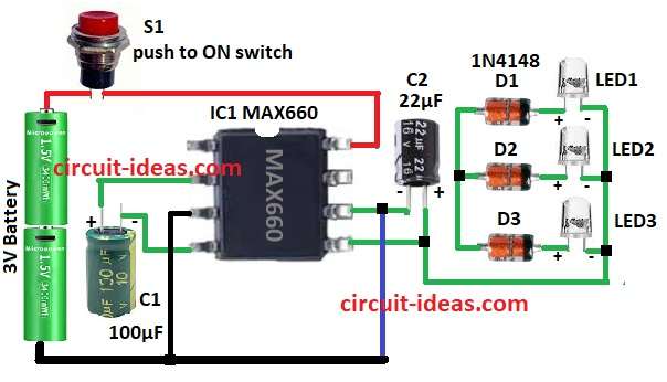
To build a Simple Boost Converter LED Torch Circuit using IC MAX660 follow the below mentioned steps for connections:
- Gather all the parts as shown in circuit diagram
- Take IC MAX660
- Pin 2 connects to positive side of C1
- Pin 4 connects to negative side of C1
- Pin 3 connects to GND
- Pin 5 connects to negative side of C2
- Pin 6 connects to positive side of C2
- Pin 6 also connect to GND
- Pin 8 connects to anode of diodes D1 to D3
- Cathode of D1 to D3 connect to anode of LEDs LED1 to LED3 in parallel
- LED cathodes connects to pin 5
- Switch S1 connect one end to pin 8 and other end to positive of 3V Battery
- Negative side of battery connect to GND
Conclusion:
This Simple Boost Converter LED Torch Circuit using IC MAX660 is small and smart.
It uses charge pump with no big coil so it is easy and tiny.
Circuit is good for flashlights, emergency lights and low for power needs.
Leave a Reply