Simple Car Fused Tail Lamp Indicator Circuit tell how to make one easy circuit for check car back lights are ON or not.
It uses one common part called resistor to know if light are getting enough power.
If light goes OFF the circuit gives an alarm to show problem.
This thing is good help to keep car lights safe and to follow rules.
What is a Car Fused Tail Lamp Indicator Circuit:
This electric circuit called car fused tail lamp indicator check if cars back lights are working or not.
It show signal when fuse for light is blown.
This circuit help driver know if there is problem in tail light like fuse gone or bulb broken.
Circuit Working:
Parts List:
| Category | Description | Quantity |
|---|---|---|
| Resistors | 10kΩ CFR 1/4 W | 1 |
| 270Ω CFR 1/4 W | 1 | |
| 470Ω CFR 1/4 W | 1 | |
| RX 0.24Ω | 1 | |
| Semiconductors | Transistors BC557 | 2 |
| Red LED 20mA 5mm | 1 |
To find resistor R value we first need voltage drop across Rx.
It should be near 400 mV for start building.
Example: car tail lights using two 10W 12V bulbs in parallel.
We use power divide by voltage (P/V) to find current which gives 1.7 amps.
Then use voltage divide by current (V/I) to find Rx which comes to 0.24 ohms.
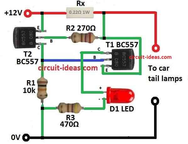
One main part in circuit is transistor T2 which is BC557.
T1 turn ON when 400 mV drop across Rx happen and then T2 goes to OFF state to cutoff.
If one tail light stop working then current in Rx become half to about 0.84 amps.
This make voltage drop to 0.2V.
T1 does not trigger with low voltage so T2 get base current from R1 and LED turn ON.
It show there is problem in tail light.
It better to use one detector circuit for small number of bulbs so fault signal work good.
Even if we use only one LED for all D1 and R3 will work together in all sensor circuits.
To work correct all T2 collector pins must connect together.
For 12V system use 470 ohm for R3 to get best LED brightness.
For 6V system use 220 ohm.
Formulas:
Below are formulas for Simple Car Fused Tail Lamp Indicator Circuit:
How to find Resistor Values:
Use this formula:
Rx = V / I
where:
- V is voltage drop
- I is current of the lamp
- R1 and R3 value depend on what voltage our circuit uses.
How to build:
To build a Simple Car Fused Tail Lamp Indicator Circuit the following steps are required to follow:
Connect Rx:
- To check how much current light is using then connect resistor Rx in series with lamps L.
Connect Transistors:
- BC557 transistor T1 must connect in way that voltage drop on Rx control it.
- When T1 is ON connect another BC557 T2 so it can turn OFF.
Add LEDs:
- When we put LED D1 it connects anode to T2 collector and cathode to ground.
- LED is in parallel with collector of T2.
Connect R1:
- Put resistor R1 between collector and base of T2 which controls base current for T2.
Common Collector Configuration:
- Join all T2 collector pins together and this will give single output signal.
Connect R3:
- Put resistor R3 in series with LED D1 which stops too much current in LED.
Power Supply Unit:
- Connect whole circuit to car battery with correct voltage 12V or 6V.
- Make condition where one light stop working and then test the circuit.
- If bulb fails then related LED must turn ON.
Modifications:
- Change resistor values if needed depend on actual use or circuit needs.
Conclusion:
This Simple Car Fused Tail Lamp Indicator Circuit is good to keep car tail lights working safe.
It can quickly show if any bulb fails by checking voltage drop on Rx.
Very useful and easy way to monitor and show cars tail lamp problem.