CFL bulb need special helper circuit to turn ON and glow bright, as this Simple CFL Driver Circuit change home electricity into power CFL can use.
Furthermore, CFL bulb uses little mercury vapor to make invisible light and then it hits special powder to make light we see.
Circuit Working:
Parts List:
| Components | Values | Quantity |
|---|---|---|
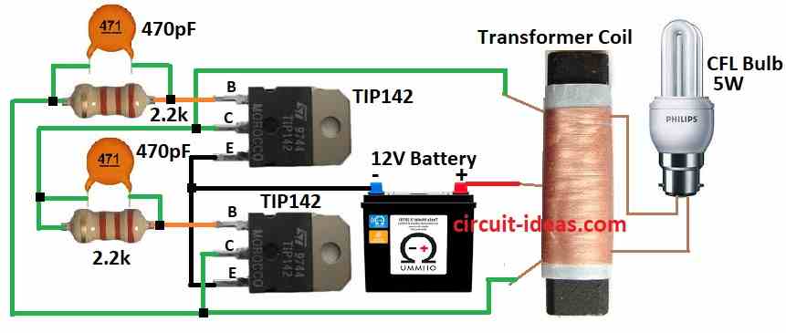
| Resistors (All resistors are assumed to be 1/4 watt) | 2.2k | 2 |
| Capacitors | Ceramic 470pF | 2 |
| Semiconductors | Transistors TIP142 | 2 |
| Transformer Coil see the text | 1 | |
| CFL Bulb 5W | 1 | |
| Battery 12V | 1 |
To begin with, two TIP142 transistors are NPN Darlington types and they can handle large currents.
Moreover, we connect them in a cross configuration, where the base of one connects to the collector of the other through a 2.2 kΩ resistor.
Also, this design make one transistor turn OFF when other is ON like push-pull.
Here, transformer is center tap and its outer wires go to transistor collectors and also center tap goes to battery positive and emitters goes to battery negative.
As a result, this way transistors switch current in transformer and make changing magnetic field.
When one transistor is ON, current flow make magnetic field one way and it creates voltage in secondary and light up CFL.
Then other transistor turns ON and current goes the other way and with this the magnetic field flip and AC keeps flowing.
CFL connect to secondary side and AC in coil light up the CFL, hence, the whole circuit works good with high efficiency and with low power use.
Working of Transformer:
This circuit run 5W CFL using 12V power.
Transformer made by winding 50 turns which then make center tap and another 50 turns added for push-pull primary.
Use ferrite rod with round or flat from old AM radio for core and secondary winding need 500 turns.
Carefully wind each layer over the previous one along the rod without overlap, people call this method “jumble winding.”
Please note that the wire enamel withstands up to (100V) only.
Use thin wire with 0.25mm or smaller and before winding put 3 layers of sticky tape on rod to stop high voltage short.
How to Build:
To build a Simple CFL Driver Circuit we need to follow the below mentioned steps:
- First, gather all the components shown in the diagram and then connect the two transistors in a cross configuration.
- Then base of first goes to collector of second with 2.2k resistor and same for other side.
- After that, connect both emitters together.
- Transformer has center tap, connect outer primary wires to transistor collectors and center tap goes to battery positive.
- Next, emitters goes to battery negative and then connect secondary side of transformer to CFL lamp.
- Be sure wires are safe and tight.
Test Circuit:
- Before final setup test the circuit and check if transistors switch and CFL lights.
- Be careful and use safety steps.
Final Setup:
- If test OK then fix all wires and cover open parts.
- High voltage is risky and if not sure ask expert or take help.
Conclusion:
To conclude, in this Simple CFL Driver Circuit it changes power to right form for CFL, as it boost voltage and gives right current and makes CFL work safe and good.
Also, it is good for saving energy.