Tiny light bulbs called LEDs get control by a special Simple Christmas LED Lights Circuit.
These circuits are same like fun DIY projects people try for make lights shine.
To make lights blink or slowly turn ON and OFF in nice way the circuit uses things like resistors and tiny chips.
By connecting LEDs in different way people can make many cool patterns.
Circuit Working:
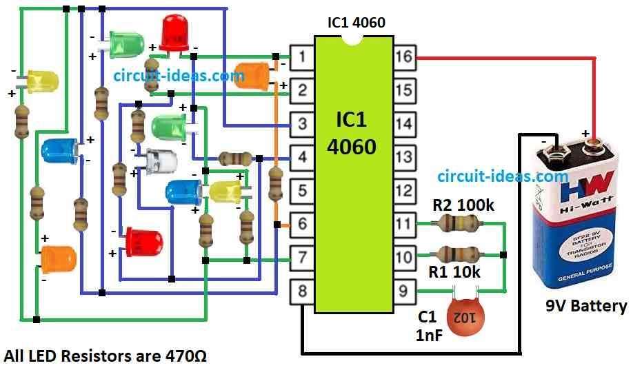
Parts List:
| Category | Description | Quantity |
|---|---|---|
| Resistors | ||
| LED resistors 470Ω 1/4 watt | 11 | |
| 100k 1/4 watt | 1 | |
| 10k 1/4 watt | 1 | |
| Capacitors | ||
| Ceramic 1nF | 1 | |
| Semiconductors | ||
| IC 4060 | 1 | |
| LEDs different color 20mA 5mm | 11 | |
| Battery 9V | 1 |
LED Christmas light circuit is simple and easy to understand.
It uses one digital counter chip IC1 type 4060.
This chip already have small oscillator inside and its speed is set by parts C1 capacitor and R1 resistor.
With these parts the oscillator run around 5 kHz.
Inside the chip this signal get divided by different numbers.
“CT” in chip diagram show how much it divide the signal to get new output speeds.
For example pin 7 CT3 output gives square wave from 5 kHz divided by 8 that mean 625 Hz.
CT4 output divide by 16, CT5 by 32 and more like that.
So each output pin gives different speed signal.
Six of these outputs connect to three LED groups and each with 11 LEDs.
Because of this LEDs blink in random style and it looks fun and colorful!
Formulas and Calculations:
IC 4060 is 14-stage chip and it work as binary ripple counter and also as oscillator.
People use it in timer and blinking circuits because it is having both counter and oscillator inside.
For Christmas LED lights blinking IC 4060 is set like oscillator as it makes clock pulses to control light flashing.
Formula to find oscillator frequency:
To know how fast it blinks we have used small formula.
This formula uses two parts connected to IC pins a resistor and a capacitor.
f = 1 / (2 × π × R × C)
where:
- R is resistor in ohms Ω and is connected to oscillator pin which is mostly pin 10.
- C is capacitor in farads F which is also connected to pin 10 and ground.
Example:
If we use:
R = 100k ohm
C = 1nF
Then:
f = 1 / (2 × 3.14159 × 100,000 × 0.000000001)
f = 1.59 MHz
So frequency is around 1.59 megahertz.
Important Points:
Pin Setup: Usually resistor and capacitor goes to pin 10 of IC 4060.
Frequency Range: Based on R and C values, chip can make very slow or very fast signals from few Hz to many MHz.
LED Blinking: This frequency decides how fast LEDs turn ON and OFF.
If we want different blinking styles then just change the resistor R or capacitor C.
By using this formula and IC 4060 in right way we can make nice patterns for Christmas lights or anything where timing is needed.
How to Build:
Below are the steps for building Simple Christmas LED Lights Circuit:
Get Circuit Board Ready:
- First take triangle shape circuit board and solder IC socket on it.
- Be careful with polarity do not put it wrong way.
- Now connect capacitor C1 and resistor R1 to the board.
- Also fix the battery clip to the board.
Put LEDs on Circuit Board:
- Place all 11 LEDs on the board.
- Watch carefully the LED legs like short leg is cathode the negative and do not mix up the sides.
Connecting:
- Now take six counter output pins from IC and connect them to LEDs.
- This will make 3 groups of LEDs and create random flashing look.
- Be sure all wires are tight and everything is connected well.
Final Check:
- Check full circuit one more time.
- Look for any loose wire or soldering mistake.
- Also check LED sides check each LED is facing right direction with correct polarity.
Getting Started:
- After all is fine connect 9V battery to battery clip.
Note:
- We will now see LEDs start blinking in fun and almost in random pattern.
- Looks very festive!
Conclusion:
This Simple Christmas LED Lights Circuit is a fun DIY project and we can change design and test new patterns.
Good for people who love both techniques and Christmas joy!
Leave a Reply