Simple Crowbar Circuit is safety part in electronics.
It protect from high voltage spike or surge.
Work like fuse but does not burns and it gets short circuit fast to stop damage.
It use SCR or TRIAC for shorting, transistor or Zener to trigger.
Trigger watch voltage all time.
If voltage is too high then trigger turn ON shorting part.
What is a Crowbar?:
Crowbar is heavy metal tool for breaking or opening things.
In electronics crowbar is safety circuit.
It stop high voltage by making short circuit like dropping metal bar on wire.
It protect other parts from damage.
Circuit Working:
Parts List:
| Component Type | Description | Quantity |
|---|---|---|
| Resistors | 1k 1/4 watt | 1 |
| Capacitors | Ceramic 0.1μF | 2 |
| Semiconductors | SCR C106 | 1 |
| Schottky Diode 10BQ030TR | 1 | |
| Zener Diode 9.1V | 1 | |
| Fuse | 1 |
Crowbar circuit protect electronic equipment from high voltage.
It always check input voltage to keep it in safe range.
If voltage goes too high (spike or surge) then circuit act fast.
It make short circuit like dropping a crowbar on wire.
Big current goes away from weak parts and into crowbar path.
Fuse also help and it breaks when current is too much.
Fuse blow and stop power and saves the rest of the circuit.
Zener diode is like brain as it watches voltage all time.
When voltage is too high then Zener tell SCR which is the special switch to turn ON.
SCR was OFF before but now its ON and makes short circuit.
Current rushes and hits the fuse and power cut is OFF.
Crowbar circuit give life to protect other parts.
Even if it needs reset or repair, after protected circuit stay safe.
Formulas:
Crowbar circuit uses some formulas to find right resistor values.
Resistor R1 control current going to Zener diode D1.
It uses ohms law to find current through R1:
I = (Vin – Vzener) / R1
where:
- I is the current in amps
- Vin is the input voltage in volts
- Vzener is the Zener voltage in volts
- R1 is the resistor value in ohms
To find power used by R1 we can use this formula:
P = I² * R1
where:
- P is the power in watts
- I is the current from first formula
- R1 is the resistor value in ohms
Note:
Capacitors C1 and C2 help remove noise and spikes.
Try different values if needed.
Fuse protect circuit from too much current.
Choose fuse just little higher than max current.
Important:
Check datasheets of parts to get correct values.
How to Build:
To build a Simple Crowbar Circuit follow the below mentioned steps:
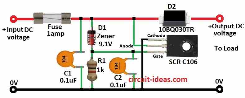
- Put all parts like in the circuit diagram.
- Connect SCR gate between 9.1V Zener diode and resistor R1.
- Connect SCR anode to positive supply.
- Connect SCR cathode to ground.
- Connect capacitor C2 from SCR gate to ground.
- Connect capacitor C1 from positive supply to ground.
- Connect fuse on positive input line of DC voltage.
- Connect diode D2 on positive output line of DC voltage.
Safety Tips:
- Be careful when working with electricity.
- Always follow safety rules.
Conclusion:
Simple Crowbar Circuit is like circuit guard.
If voltage too high then it short fast and blows the fuse.
It stops power and protect other parts.
We should know electronics before making it and stay safe.