To begin with, this Simple Current Limiter Circuit using Transistors gives tutorial to show how to make a circuit that stop giving too much power to other electronics.
Also, it helps to protect from overload by using two transistors and one special resistor.
What is a Current Limiter Circuit using Transistors:
A transistor current limiter circuit stops too much current connects through load so no overcurrent problem happen, so this type circuit uses some electric parts and power source to keep things safe from high voltage damage.
Circuit Working:
Parts List:
| Components | Values | Quantity |
|---|---|---|
| Resistor R1 | 1/4 W CFR | 1 |
| Resistor R2 | High watt resistor as calculated | 1 |
| Transistor T1 | High watt NPN transistor | 1 |
| Transistor T2 | Any transistor 2N2222 | 1 |
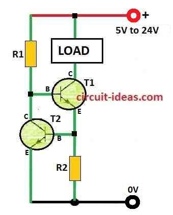
In the above circuit, T1 is the main part that controls current and load help to check how much current goes through T1 and T1 stop it if there is too much of load, this is how T1 work.
Therefore, T1 can send current to load because its base connects to positive power and when current get too high voltage on sense resistor goes up.
Also, this higher voltage goes to base of T2 through emitter of T1 and then T2 start working because of this high voltage.
Lastly, T2 send T1s base current to ground so T1 cannot give more current and that is how current stays limited.
Formulas and Calculations:
Use this formula to find the value of R1, for example we used a 100-watt LED as the load.
R1 = (Us − 0.7) × Hfe / Load Current
where:
- Us is power supply voltage
- Hfe is current gain of T2
- Load current is same as LED current
LED current = 100W / 35V = 2.5 amps
Now put values in formula:
R1 = (35 − 0.7) × 30 / 2.5 = 410 Ω
To find power rating of resistor:
P = V² / R = 35×35 / 410 = 2.98 or almost 3 watts
Now for R2:
R2 = 0.7 / LED current
LED current is 2.5 amps
So R2 = 0.7 / 2.5 = 0.3 Ω
Power of R2 is:
0.7 × 2.5 = 2 watts
Note:
T2 act like current limiter by checking voltage drop on current sensing resistor, if there is too much current then T2 stops T1s base current and this reduces current from T1 to load.
People also use this kind of circuit in power supplies and protection systems to protect components from high-current damage.
How to Build:
To build a Simple Current Limiter Circuit using Transistors we would need to follow the following steps.
Know the Transistor Pins T1 and T2:
- First, transistor have 3 pins collector, base and emitter.
- Next, connect T1 collector to positive side of load like LED and connect T1 emitter to ground.
- After that, T2 collector connects to T1 base and T2 emitter also connects to ground.
- Then T2 base connect at point between T1 emitter and resistor R2.
- Also, one side of R2 connects to T1 emitter and other side to ground.
Power Connections:
- Next, connect positive (+) from power supply to T1 base through resistor R1.
- And Negative (−) of power supply connects to ground.
Use Formula to Find R1 and R2:
- R1 = (Us − 0.7) × Hfe / Load Current
- Use this formula to find R2: R2 = 0.7 / load current here, Us means the supply voltage, Hfe means the gain of T2 and load current means the current the LED or other load needs.
Wire Resistors Correctly:
- R1 connect between power supply and T1 base and R2 connect between T2 base and ground.
Testing the Circuit:
- Once power is ON watch the LED or other load and try different loads to check if current limiting work properly.
- Hence, if circuit does not work right then change resistor values or try other transistors.
Important Tips:
- First, choose transistors that can handle our voltage and current.
- Then pick standard resistor values near the calculated ones and be sure resistors can handle power loss (watts).
- Also, be very careful if working with high voltage or high current it can be dangerous.
Conclusion:
To conclude, Simple Current Limiter Circuit using Transistors is strong and easy way to protect sensitive parts from too much current.
Also, this simple circuit with transistor help stop damage by controlling how much current goes through, which keeps current at safe level.
Finally, how the circuit work can change by depending on which transistors and parts we use and also we can adjust it for different uses.
Leave a Reply