LED turn ON by LDR when dark and LDR and resistor connect in voltage divider circuit.
During bright light transistor base get low voltage so transistor stay OFF and during dark come LDR resistance goes down and base voltage goes up with transistor turn ON and LED light up.
Hence, this Simple Darkness Detector Circuit is easy to make and needs few parts only.
Circuit Working:
Parts List:
| Components | Values | Quantity |
|---|---|---|
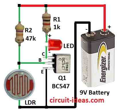
| Resistors | 1k 1/4 watt | 1 |
| 47k 1/4 watt | 1 | |
| Semiconductors | Transistor BC547 | 1 |
| Photoresistor LDR | 1 | |
| LED any 5mm 20mA | 1 | |
| 9V Battery | 1 |
To begin with, LDR is main part of this circuit and it work like dimmer switch and changes resistance with light.
Also, in bright light LDR has high resistance and in dark it has low resistance, hence, to make voltage divider connect LDR with resistor R2 and together they split voltage from power source.
During bright light LDR block voltage to transistor base so transistor stays OFF and this transistor work like switch and this small voltage at base can control big current.
When at dark the LDR resistance goes down and more voltage goes to transistor base and then transistor turns ON and completes the path and LED lights up.
So LDR controls transistor like switch and when dark come the LDR turns ON the LED.
Formula:
The voltage divider, consisting of the LDR and the fixed resistor, show the transistors base voltage, therefore, we use the following formula to calculate the base voltage:
Vout = Vin × (R2 / (LDR + R2))
where:
- Vout is the voltage at transistor base
- Vin is the voltage from power supply
- R2 is the fixed resistor like 47k
- LDR is the LDR resistance which changes with light
How to Build:
To build a Simple Darkness Detector Circuit follow the below mentioned steps for connections:
- First, take all parts shown in circuit diagram.
- Next, connect transistor Q1 collector to +9V through resistor R1 and LED, connect transistor base between resistor R2 and LDR and then connect emitter of Q1 to ground.
- After that, connect resistor R2 and LDR from +9V to ground.
Conclusion:
This Simple Darkness Detector Circuit is easy to make and is quite useful, as this circuit is good for first electronics project which need few parts only.
Furthermore, we can use this small circuit in other big projects too, also hope with this project it gives us an idea to make our own darkness detector.
Leave a Reply