If our device need right DC power to work safe then this Simple DC High Low Voltage Cut Off Circuit work like a guard.
Also, if battery is too low then circuit stop power to save our device and if battery is too high then also circuit stops power to protect.
Hence, this circuit keep device safe from bad battery power.
Circuit Working:
Parts List:
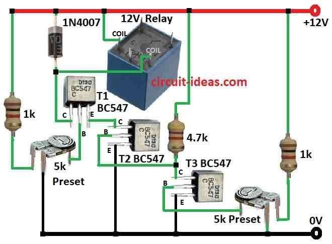
| Components | Values | Quantity |
|---|---|---|
| Resistors (All resistors are 1/4 watt unless specified) | 1k | 2 |
| 4.7k | 1 | |
| Preset 5k | 2 | |
| Semiconductors | Transistor BC547 | 3 |
| Diode 1N4007 | 1 | |
| Relay 12V | 1 |
This circuit has 3 BC547 transistors and each one works like a small switch, transistors stay ON by default because of base resistors.
Also, two variable resistors set the cut-off voltages with one for low and one for high and they connect to battery voltage through 4.7k and 5k resistors.
Furthermore, if the voltage becomes too high, the middle transistor turns OFF and if the voltage becomes too low, the left transistor turns OFF.
These two transistors control the relay and if either one turns OFF, the relay also turns OFF and cuts power to the device.
Circuit Problems:
No hysteresis as relay may switch fast again and again if voltage is not stable, no base resistor as it may damage transistor.
Also, no reverse polarity protection if there is wrong connection then it can harm the circuit.
Still its a simple way to stop power when voltage is too high or low.
Formulas:
Simple DC High/Low Cut-Off Circuit Using Formula and we can make easy voltage cut-off circuit using voltage divider formula:
Vout = Vin × (R2 / (R1 + R2))
where:
- Vout is the voltage where circuit cuts power
- Vin is the battery voltage for input voltage
- R1 is the first resistor in diagram 1k + top part of preset
- R2 is the second resistor in diagram with bottom part of preset
How to Build:
To build a Simple DC High Low Voltage Cut Off Circuit follow the blow steps for connection:
- First, follow the circuit diagram and collect all parts and then put all the parts on PCB as per schematic.
- Next, set them based on our use and then connect adjustable DC power supply.
- Now slowly increase voltage and watch relay turn ON at high cut-off and then lower the voltage and relay should turn OFF at low cut-off.
- After that, check all connections before power ON and start with low voltage which go up slowly.
- Also, use correct voltage and current rated parts and if not sure ask for expert help.
Conclusion:
In this Simple DC High Low Voltage Cut Off Circuit for better safety we need to add hysteresis, base resistors and reverse polarity protection.
Finally, for more details read the full datasheet or ask electronic expert for any help.
Leave a Reply