This Digital Volume Controller Circuit talks about special type of electronic volume control.
It does not uses normal knob but it uses an electronic parts.
Normal volume knob uses resistor but this one uses small computer chip to control sound level.
It gives more function and also with more correctly.
Circuit Working:
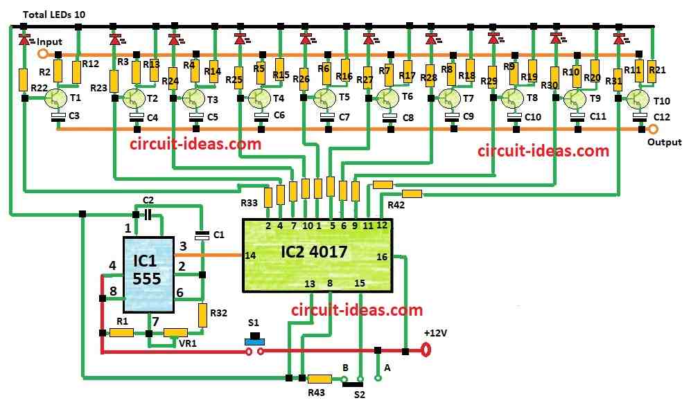
Parts List:
| Category | Quantity |
|---|---|
| Resistors (All resistors are 1/4 watt) | |
| R1, R2, R20, R32 22k | 4 |
| R3 18k, R4 15k, R5 10k, R6 8.2k, R7 5.6k, R8 4.7k, R9 1k, R10 300Ω | 1 each |
| R11 1Ω, R12 300Ω, R13 1k, R14 15k, R16 8.2k, R17 10k, R18 15k, R19 18k | 1 each |
| R21 47k | 1 |
| R22 to R31, R33 to R43 10k | 21 |
| Preset VR1 47k | 1 |
| Capacitors | |
| C2 Ceramic 0.1μF | 1 |
| C1 Electrolytic 10μF 25V | 1 |
| C3 to C12 Electrolytic 1μF 25V | 10 |
| Semiconductors | |
| Red LED1 to LED10 5mm 20mA | 10 |
| Transistors T1 to T10 BC547 | 10 |
| IC1 555 and IC2 4017 | 1 each |
| S1 Push-to-on switch | 1 |
| S2 1 pole 2-way switch | 1 |
IC2 4017 decade counter and many transistors work together to make this circuit work.
Transistors take input at collector side and give output from emitter side.
IC2 4017 give signal to transistor and make it reach full output at right time.
Signal goes to amplifier through emitter and one capacitor and this capacitor remove DC part.
Same transistor T2 turn ON fully when pin 4 of IC2 4017 goes high and then signal goes straight to output through collector resistor.
To start press switch S1.
Timer IC1 555 make pulse again and again and send it to IC2.
IC2 4017 output decide which transistor turn ON.
Stop pressing switch when volume become okay.
Switch S2 at point A to reset the counter.
Below formula is used to change time of output pulses.
Formula:
The time constant Td of this circuit is mostly used in timer circuit which is shown in below formula:
Td = 0.693(R1 + 2√R1 + 2R3²) C1 seconds
here:
- Td is time constant in seconds.
- 0.693 is fixed number it comes from how capacitor charges with time.
- R1 is resistor whose value is in ohms.
- √R1 means square root of resistor R1.
- 2R3² means resistor R3 multiply by itself two times then multiply by 2.
- C1 is capacitor and its value is in farads.
How this formula work:
This formula tell how long capacitor C1 takes to charge.
R1 and R3 control how fast it charges.
Just small explanation here:
If R1 or R3 become big:
Then capacitor charges slowly so Td becomes bigger.
If C1 is bigger:
Then also capacitor take more time to charge fully so Td increases.
How to Build:
To build a Digital Volume Controller Circuit follow the below steps:
Schematic Design:
- Make PCB or Breadboard Setup:
- Arrange all parts on PCB or on breadboard.
Connect ICs:
- Join IC 4017 and IC 555 to power supply Vcc and GND properly.
- Pin 4 of IC 4017 should connect to transistor base or other good input point.
Transistor Connection:
- Join transistors T1 and T2 in circuit as per their job in switching.
Place Resistors:
- Put resistors R1, R2 and R3 in right order with correct values.
Connect Capacitors:
- Join capacitor C1 and one coupling capacitor to block DC and send signal properly.
Switches:
- Wire switches S1 and S2 and S1 to start and S2 for reset counter.
Amplifier and Preamplifier:
- Check connection between pre- amp output and amplifier input.
Power Source:
- Give needed voltage to Vcc pin to power the circuit.
- Check every connection two times.
- Turn ON circuit and see if it works correct.
- Use oscilloscope or any other tool to check if circuit does the right thing.
Make Changes if Needed:
- If something is not right then change circuit to make volume control and switching better.
- Always check component datasheets to avoid mistake.
- If we not know much about electronics then better ask expert or someone who knows.
Conclusion:
This Digital Volume Controller Circuit gives good control for remote use and can connect to digital audio system.
It is used in home theater, speaker system, audio amp and other place where auto or digital sound control are needed.