This circuit is a Simple Diode and Transistor Based Audio Limiter Circuit and we use it in audio systems where signal level must stay under safe limit.
Most power amplifiers require an input signal of around (1Vrms) and if the signal exceeds this level, the amplifier can distort the sound or even damage itself.
Audio signal generator sometimes gives high amplitude output and it may convert sine wave into distorted waveform like square wave when overload happens.
Hence, this creates bad sound and can also harm amplifier and speaker.
So we place this limiter circuit between signal source and power amplifier; as this circuit controls high voltage audio peaks and keeps output safe near 1Vrms.
Circuit Working:
Parts List:
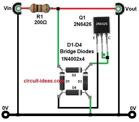
| Components | Values | Quantity |
|---|---|---|
| Resistor | 200Ω 1/4W | 1 |
| Semiconductors | Bridge Rectifier 1N4002 150mA | 4 |
| Transistor 2N6426 | 1 |
First, audio input signal enters through resistor R1, then this R1 reduces current and protects circuit from sudden high input spikes.
Then signal goes into diode bridge D1 to D4 and these four diodes work like full wave rectifier, as they convert AC audio signal into pulsating DC signal.
We use bridge rectifier because transistor Q1 responds to DC level, not direct AC waveform.
Now when input signal is small (below around 1Vrms), diode bridge output voltage stays low.
Hence, Q1 does not turn ON; so audio signal passes normally to output without much distortion.
When input signal becomes higher than 1Vrms then rectified voltage becomes high enough to trigger base of Q1.
Q1 then turns ON strongly and because Q1 is Darlington transistor, it gives very high gain, as it conducts heavily between collector and emitter.
When Q1 conducts, it effectively creates a low resistance path and it shunts or clamps the signal level.
So the output signal cannot rise further and stays limited near a safe level.
This action protects power amplifier input from over-voltage.
In simple words:
Low signal turns Q1 OFF and signal passes normally.
High signal turns Q1 ON and Q1 clamps and limits the signal.
How to Build:
To build a Simple Diode and Transistor Based Audio Limiter Circuit follow the below connection steps:
- First, start by gathering all the circuit parts as in diagram above.
- Next, take R1 resistor and connect between audio input (Vin) and bridge diode input.
- After that, take bridge diodes D1-D4 and connect in diamond shape as in circuit diagram.
- Two diodes conduct at a time depending on signal polarity and output nodes with one node goes to ground and one node goes to transistor base control path
- Then take Q1 transistor with emitter pin and connect between diode D3 and D4.
- Collector pin connect between diodes D2 and D3.
- Base pin connect to collector of transistor Q1.
Conclusion:
This Simple Diode and Transistor Based Audio Limiter Circuit protects audio systems from high voltage signals.
Also it keeps output signal safe near 1Vrms level and it prevents distortion and also avoids damage to amplifier and speaker.
Circuit uses simple parts like resistor, diode bridge and 2N6426 transistor; also it does not need complex IC or power supply regulation, it works automatically based on signal level.
When input stays low, circuit allows clean audio pass and when input goes high, circuit activates and limits the signal.
Finally, this circuit works like simple audio safety guard for any audio system.