EMS circuit… it like machine using electric stimulator to make muscle go move.
It have many small electronic thing like time keeper, signal maker, power booster and sticky pad.
This Electronic Muscle Stimulation Circuit send little shock, not hurt but through sticky pad on skin on top muscle.
This small shock like brain talk to muscle make muscle squeeze and then relax again.
Circuit Working:
Parts List:
| Component | Quantity |
|---|---|
| Resistors (All resistors are 1/4 watt unless specified) | |
| 180k | 1 |
| 1.8k | 1 |
| 2.2k | 1 |
| 100Ω | 1 |
| Potentiometer 4.7k | 1 |
| Capacitors | |
| Ceramic 100nF | 1 |
| Ceramic 0.01µF | 1 |
| Semiconductors | |
| IC 555 | 1 |
| Transistor BC557 | 1 |
| Transistor 2N2907 | 1 |
| Diode 1N4007 | 1 |
| LED 5mm, 20mA | 1 |
| ON/OFF Switch | 1 |
| Battery 3V | 1 |
| Transformer 12V to 220V, 100mA to 150mA | 1 |
This system have two parts one is muscle stimulator and other is time keeper.
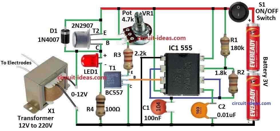
Electronic Muscle Stimulator Circuit (EMS) shown in above circuit diagram uses IC 7555.
It work like signal maker (astable) give fast pulse which is around 80 times per second.
If we turn small knob VR1 than we can change how strong the electric feel on skin.
LED1 light more bright when pulse is strong.
If want more strong stimulator one can change 1.8k ohm resistor to bigger one maybe up to 10k.
X1 is small transformer which take 220V in big side and give 12V, 100 to 150mA on small side.
But here we can connect transformer backward like small wire side is connected to T2 and ground while big wire side connects to stimulator pads.
Output voltage go near 60V but do not worry current is very small so there is no danger for shock.
Electrodes are small metal pieces around 2.5 by 2.5 centimeter.
They connect with soft wire soldered to circuit output.
Before use clean metal plates with wet cloth.
Then put electrodes on body tie with elastic or velcro.
After that turn ON the circuit with switch S1 and slowly move VR1 knob until one feels little tingle on skin
Formula and Calculations:
This formula below can help to believe frequency (f) and duty cycle (D) for astable multivibrator using 555 IC:
Frequency (f):
How fast it blink or switch is depend on value of resistors R1, R2 and capacitor C.
These parts connect outside to the 555 IC and decide how quick it go up and down in astable mode.
f = 1.44 (R1+2 * R2) * C
here,
- R1 is resistor going from pin 7 discharge pin to Vcc power line
- R2 is resistor between pin 6 threshold and pin 7 discharge.
- C is capacitor connect to pin 6 and pin 2 threshold and trigger and also pin 7.
Duty Cycle D:
We can use this formula to imagine duty cycle, it mean how much time output stay high during full wave:
D = (R1 + R2) / (R1 + 2R2)
This formula will tell how big part of full time the signal stay ON high.
f = 1.44 (R1 + 2R2) * C
f = 1.44 / [180+(2 * 1.8)] * 0.0000001
= 78431Hz
= 78.431kHz
So the frequency f of oscillation will be around 78.431 kHz
Duty Cycle Calculation:
D = (R1 + R2) / (R1 + 2R2)
D= (180+1.8) / [180+(2*1.8)]
D = 0.99
So duty cycle is almost 99% like very high time ON.
With this math using value of outside resistors and capacitor one can imagine easy the frequency and duty cycle of output wave from IC 555 in astable mode.
If want to change how fast or how long signal stay high just change R1, R2 and C.
This will help make signal good for ones EMS (muscle stimulator) project.
How to Build:
To build a Electronic Muscle Stimulation Circuit do the following steps below:
- First put IC 7555 on the board.
- Check it face the right way.
- Put 1.8k resistor between correct legs of IC 7555.
- If want more strong stimulator one can use bigger resistor instead.
- Add potentiometer VR1 and place it where one can turn easy.
- Connect LED1 be sure plus and minus side is right.
- Put transistor T2 on board same like in diagram.
- Connect transformer X1 and be careful with small wire side and big wire side connected to correct place.
- Use soft wire to connect electrodes to board.
- Solder all wires strong so they wont fall off.
- Before use clean electrode metal with wet cloth.
- Fix the board and parts inside some box or case.
- Put switch S1 on the case where easy to ON/OFF.
- Tie elastic bands on box so electrodes can stay on body.
- Check all wires are tight and and covered properly and also check for short circuit if any.
- Try the circuit see how it works.
- Turn VR1 to change how strong the stimulator feel.
How to Use:
- Put the electrodes on body where one want and use elastic band and velcro to keep in place.
- Turn ON the circuit by flip switch S1.
- Slowly turn VR1 knob until one feels small tingle feeling.
- Use the device for muscle moving as one needs but be safe.
Important:
- Be careful with electricity and hot soldering tool.
- Always follow safety rules.
- Be sure wires are covered and ground is correct, so no shock or anyone gets hurt.
- If not sure about electronic, ask help from person who know electronics better.
Conclusion:
Electronic Muscle Stimulation (EMS) circuit give way to move muscle without cut or pain.
It can help for therapy and body fitness.
But must use careful and with right advice.
Very important to control how strong the stimulator is and where one put the pads so no bad effect happen.
References:
Development of a Circuit for Functional Electrical Stimulation