To begin with, this article for Simple ESR Meter Circuit show how to make one tool for checking capacitor in phone, laptop and other device.
Capacitor work like small battery and it keep some power inside, also we can find bad capacitor without removing it from circuit board and for that we need to use one tool called ESR meter.
Hence, this meter uses one common chip named as 555 IC and one special gauge to see small change in voltage.
What is a ESR Meter Circuit:
An ESR meter checks a capacitors Equivalent Series Resistance (ESR), a crucial measurement that reveals internal resistance during high frequency operation.
Also, it helps to find bad or damaged capacitor in circuit so checking ESR is very useful.
Understanding ESR:
ESR or Equivalent Series Resistance mean small resistance that stay in series with perfect capacitor and finding problem in electrolytic capacitor is common problem in electronics.
Also, normal multimeter or capacitor meter does not always show this problem, but if we check through ESR it can show if capacitor is bad.
When capacitor get damage, its ESR go high, so device may not work properly, even if capacitance still look okay.
Good things about ESR Meter:
This ESR meter is useful because we do not need to remove capacitor from board to check it, but to stop other parts from messing with reading the test voltage must stay low.
Further we can find high ESR even if capacitor still have good capacitance, as normal capacitance meter maybe not work good for checking capacitor on board like this.
Circuit Working:
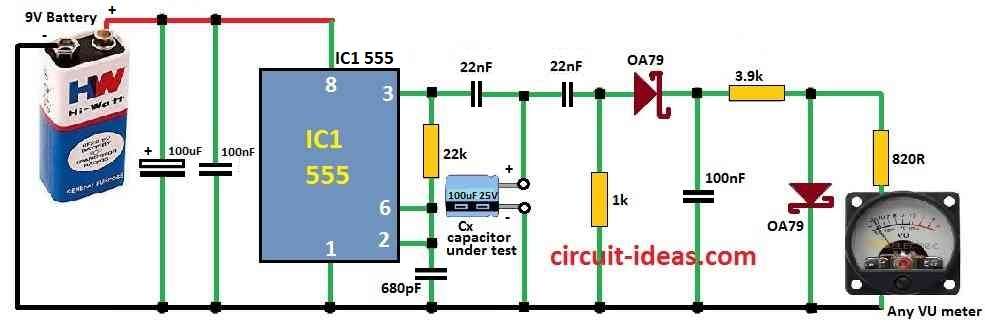
555 IC make high frequency current around 50 kHz and this current connects to the capacitor we want to test.
Analog meter check the voltage drop (Vdrop) on the capacitor.
Diode D1 takes only the positive side of the AC signal for a correct reading, while diode D2 protects the analog meter from too much voltage when no capacitor is connected, so the meter lasts longer.
Parts List:
| Components | Values | Quantity |
|---|---|---|
| Resistors | All resistors are 1/4 W MFR | |
| 22k | 1 | |
| 1k | 1 | |
| 3.9k | 1 | |
| 820Ω | 1 | |
| Capacitors | ||
| PPC 680pF | 1 | |
| PPC 100nF | 1 | |
| PPC 22nF | 2 | |
| Cx capacitor Under test | 1 | |
| Electrolytic 100µF | 1 | |
| Electrolytic 100nF | 1 | |
| Semiconductors | ||
| Germanium diode OA79 | 2 | |
| IC 555 | 1 | |
| Battery 9V | 1 | |
| VU Meter Any type | 1 |
How to Build:
To build a Simple ESR Meter Circuit follow the below steps for connection process:
- First, build the circuit using 555 IC to make high frequency current.
- Then connect analog meter to measure voltage drop across the capacitor.
- Thus, to get correct reading and to protect the meter, add diode D1 for rectifying and D2 for safety.
- Next, choose resistor R1 and R2 value carefully based on what the analog meter needs.
- Also, keep the test wires short so resistance and inductance not affect the reading too much.
- Lastly, like in the circuit diagram use double wires to connect the capacitor we want to test.
Formulas and Calculations:
Some formulas help to understand better when making simple ESR meter circuit:
What is ESR:
ESR (Equivalent Series Resistance) is important part in capacitor and it is:
ESR = Requivalent − Rideal
where:
- Requivalent is real resistance inside capacitor.
- Rideal is perfect resistance which is almost zero if capacitor is ideal.
Knowing ESR Change:
The following formula shows how ESR changes with time:
ΔESR / Δt ∝ ΔR / Δt
This mean when capacitor get old or bad ESR goes up and this can make electronic device not work right.
Why ESR Meter is Good:
Ohms law links the voltage drop across a capacitor, commonly called the “drop” to its Effective Series Resistance (ESR)
ESR = Vdrop / I
where:
- I is the current going through capacitor.
Setting the Meter Scale:
Make the meter scale using ESR values from new capacitors and use log scale like:
1µF, 10µF, 100µF, 1000µF
This help show different ESR levels better on analog meter.
Power:
The ESR meter uses one 9V battery for power and it take around 6 mA when not testing and up to 16 mA when checking capacitor.
Conclusion:
Overall, electronics repairers find the Simple ESR Meter Circuit a very useful tool, often using it more than a standard multimeter.
This DIY ESR meter is simple but works good and helps to find bad electrolytic capacitors, also it is very helpful for anyone doing electronics repair.
OA79 is a germanium diode!!! Not Schottky diode!!
Thank you for your suggestion, I have corrected it accordingly.