Like our previous post on low and medium impedance preamplifier circuits, this tutorial shows a simple JFET preamp circuit that gives very high input impedance.
The circuit works good with weak signal sources like microphone, guitar pickup or sensor and also it uses a N-channel JFET 2N5457.
This Simple High Impedance JFET Preamp Circuit is small, low cost and easy to build, also it improves signal level before sending to power amplifier.
Circuit Working:
Parts List:
| Components | Values | Quantity |
|---|---|---|
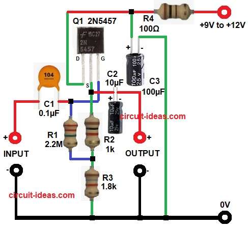
| Resistors | 2.2M, 1k, 1.8k, 100Ω | 1 each |
| Capacitors | Ceramic 0.1µF | 1 |
| Electrolytic 10µF, 100µF | 1 each | |
| Semiconductors | N-channel JFET 2N5457 (or equivalent) | 1 |
| Power Supply +9V to +12V DC | 1 |
First, 9V to 12V DC supply comes in, R4 and C3 make filter with R4 limits current and C3 removes noise, so circuit gets clean DC.
Next, this voltage goes to drain (D) of FET 2N5457 and input signal comes through C1 and this C1 blocks DC and passes only AC to gate (G).
Now, gate bias is important, so no need of separate negative voltage.
Also, here circuit uses self-bias with R1 connects gate to junction of R2 and R3 so bias stays stable.
Then, current flows through FET and R2, R3, because of this, voltage develops at source (S) and so source becomes positive.
Gate is near 0V and source is positive, so gate becomes negative with respect to source and this makes correct Vgs and FET works properly.
Next, R2 and R3 control bias and gain and if we change their values, gain and bias also change, then amplified signal appears at drain.
After that, signal goes through C2 and this C2 blocks DC and passes amplified AC to output.
Also, R1 connects to moving voltage point, so bootstrapping happens and this increases input impedance to very high which is to mega ohms, so its good for weak signals like mic or guitar.
Output impedance is medium which is few hundred ohms, so it can drive next stage.
Finally, we can change R3 from 1.5k to 4.7k for low voltage supply and this helps to adjust bias and improve performance.
How to Build:
To build a Simple High Impedance JFET Preamp Circuit follow the below connection steps:
- First, start by gathering all the circuits parts as in diagram above.
- Next, take N-channel JFET Q1 2N5457 and connect gate to C1 and R1
- Source connects to R2 and R3 and drain connects to supply through R4 and also to C3.
- After that, connect capacitor C1 one side connect to gate of FET and other end to +INPUT signal
- And -INPUT signal goes to ground.
- Then connect resistor R1 one side to gate and other side between resistor R2 and R3.
- Now connect resistor R2 and R3 in series from source pin and ground.
- Next, capacitator C2 positive end connect from source pin and negative end to +OUPUT
- And -OUTPUT goes to ground.
- Then connect resistor R4 between Vcc and drain pin.
- Lastly, capacitor C3 positive end goes to Vcc lin and negative goes to ground line.
Conclusion:
This Simple High Impedance JFET Preamp Circuit is easy and useful as it gives high input impedance and good signal amplification.
Moreover, we can use it for audio, guitar and sensor signals.
Also, it needs very few components and easy wiring, so beginners can build it without difficulty.
Leave a Reply