Anyone can make its own wireless headphones using this Infrared Wireless Headphone Circuit.
It sends sound by using infrared light but not with wire.
So we can move around easily while listening.
We can also control it from far like change volume or songs.
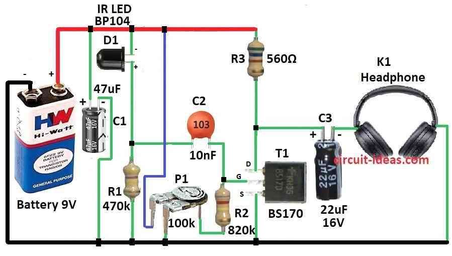
What is a Infrared Headphones Receiver Circuit:
Main job of infrared (IR) headphones receiver circuit is to get wireless audio signal sent by infrared light.
Infrared headphones are with no wire headphones.
They get sound from TV or music system using infrared.
Receiver circuit is very important as it catches the signal and change it back to sound where we can hear.
Circuit Working:
Parts List:
| Category | Description | Quantity |
|---|---|---|
| Resistors( All resistors are 1/4 watt) | 470k | 1 |
| 820k | 1 | |
| 560Ω | 1 | |
| Preset 100k | 1 | |
| Capacitors | Ceramic 10nF | 1 |
| Electrolytic 47μF 16V | 2 | |
| Electrolytic 22μF 16V | 2 | |
| Semiconductors | Transistor BS170 | 1 |
| IR receiver LED BP104 | 1 | |
| Headphone | 1 | |
| Battery 9V | 1 |
Use both IR headphones transmitter and IR headphones receiver.
Choose headphones with 600 ohm impedance.
BPW41N and BP104 have light filter that focus at 950 nm when temperature is 25°C.
This IR receiver idea is simple so little sound distortion (1% to 2%) happens at 3 to 4 meter distance in normal light then that is okay.
How to Build:
To build a Infrared Wireless Headphone Circuit following are the below mentioned steps to be followed:
Find the Parts:
- Choose good infrared photodiode that match what we need.
- Be sure headphones work with receiver and have right impedance.
Make the Circuit:
- Build easy circuit by using parts for matching impedance and add photodiode amplifier if needed.
- Use filter to let in only infrared light which blocks the normal light.
Put Circuit Together:
- Use breadboard or PCB to build circuit.
- Connect all parts same like in circuit diagram.
Connect IR Transmitter:
- Join IR transmitter and receiver together.
- For good signal be sure both face each other with no block in between.
Power Source:
- Give power from right source.
- Check if power is enough for all parts.
Test the Circuit:
- Test the receiver in normal room light from 3 to 4 meter height.
- Use tool to check sound distortion.
Fix and Improve:
- If needed change the circuit to work better.
- Change amplifier gain or settings to get good sound.
Final Test:
- Test everything is well in different conditions to be sure it works strong and stable.
Keep Record:
- Write down all connections of final circuit for any changes we have to make for later use.
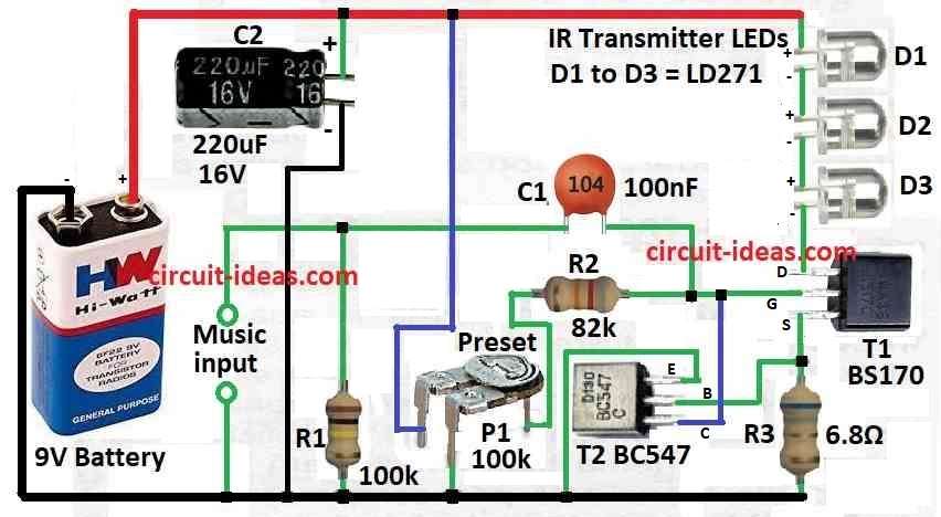
What is a Infrared Headphones Transmitter Circuit:
Infrared headphones transmitter circuit uses electricity to send sound without wire to IR headphones.
This transmitter circuit is an important part which sends sound from source to headphones using infrared light.
Circuit Working:
Parts list:
| Category | Description | Quantity |
|---|---|---|
| Resistors( All resistors are 1/4 watt) | 100k | 1 |
| 82k | 1 | |
| 6.8Ω | 1 | |
| Preset 100k | 1 | |
| Capacitors | Electrolytic 220μF 16V | 1 |
| Ceramic 100nF | 1 | |
| Semiconductors | Transistor BC547 | 2 |
| Transistor BS170 | 2 | |
| IR transmitter LED LD271 | 3 | |
| Battery 9V | 1 |
Transmitter help headphones connect using light from infrared.
Three IR LEDs get power from transistor T1 which we can adjust current with preset P1.
When using 9V power this IR transmitter takes around 60mA current.
Keep adapter ground away from audio signal ground, so no bad current goes through LEDs.
Put LEDs in different angles and use reflectors behind them to make light signal better because it goes mostly in one direction.
Best sound input for this transmitter is 100 to 200 mV.
It can work up to 1.2 to 2.4 meter distance.
We also give the IR receiver circuit for this transmitter.
Formula:
This is a common formula to find voltage gain (Av) of FET amplifier:
Av = −gm * RL
where:
gm is transconductance of FET found by:
gm = 2ID / (VGS − Vth)
- ID is drain current of FET.
- VGS is gate source voltage.
- Vth is threshold voltage of FET.
- RL is load resistor at drain side.
Why this formula works:
Gm Transconductance:
This show how much output current of FET changes when input voltage of VGS changes.
It tell how strong FET can amplify signal.
RL Load Resistance:
This resistor is at FET output for drain
It affect how much voltage gain we get from amplifier.
How to Build:
To build a Infrared Wireless Headphone Circuit follow the below steps for connections:
Find the Parts:
- Choose good infrared LEDs, a preset P1 to change current and one transistor T1 for giving current to LEDs.
- Pick resistors, capacitors and other parts as per circuit design.
Make the Circuit:
- Draw simple circuit with audio input, current adjust part and transistor to power the LEDs.
- If we want to use reflectors decide where to put them for better light direction.
Build the Circuit:
- Use breadboard or PCB to make the circuit.
- Connect all parts same like shown in diagram.
Connect Audio Input:
- Connect audio source like TV, music player to the transmitter circuit.
Power the Circuit:
- Give power from battery or adapter with right voltage.
Adjustments:
- Use preset P1 to change current going through the LEDs.
- Tune circuit for best working.
- Use IR headphones and receiver to test.
- Check how far signal goes and how good the sound is.
Conclusion:
This Infrared Wireless Headphone Circuit gives wireless music and also lets us control audio without wires.
Good for places where people want to move around and still hear sound or control music.
It can be changed based on what we need or what setup we have.
Leave a Reply