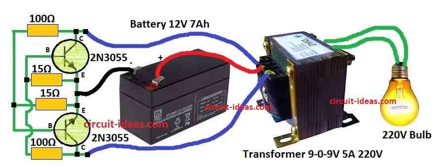
In this post we show how to make an easy and simple Inverter Circuit using Two 2N3055 Transistors, which works with 12V battery and gives around 100 watt 220V AC power.
Also this circuit is good for using with small home devices.
Circuit Working:
Parts List:
| Components | Values | Quantity |
|---|---|---|
| Resistors | 100Ω 10W Wire Wound | 2 |
| 15Ω 10W Wire Wound | 2 | |
| Semiconductors | 2N3055 Transistor | 2 |
| Transformer as per diagram | 1 | |
| Battery as per diagram | 1 |
This inverter work like saturable core oscillator which uses one filament transformer and two normal germanium power transistors.
Also, transistors connect like multivibrator style for feedback and make it oscillate and it take power from car battery.
Furthermore, transformer is very important in this circuit because it help change voltage up or down for inverter to work.
Germanium transistors act like switch which turn ON and OFF to make AC output.
In full load inverter give about 75% efficiency and output voltage goes around 220V.
Also, to stop spikes in output, we use a small Pi filter, so output wave becomes trapezoid instead of square.
Hence, this is better for radios, recorders and other electronics, efficiency, frequency, voltage and start power all depend on each other.
Further, try different bias resistors like R1 to make it better and this bias resistors for both transistors must match or else wave will become bad.
After building the circuit turn ON and check if it works good and use multimeter to check output voltage.
And if not good then adjust parts for better result, also we need good circuit diagram with all values and connections for actual building.
Also, better to understand how inverter work before making and read description slowly it show how everything works.
Formulas:
First, this cross-coupled transistor inverter work like flip-flop or bistable multivibrator and it does not need capacitor but only uses resistors for timing.
In this circuit frequency does not depend on charging/discharging capacitor, as it depend on transistor property and resistor timing.
For example time delay come from resistor and transistor speed, that decide how fast flip-flop switches ON and OFF.
Frequency (f) in this circuit is:
f = 1 / (2 * R * Ceff)
here,
- f is frequency in hertz Hz
- R is resistor value in ohms Ω
- Ceff is effective capacitance from transistor inside parts like junction capacitance
Value of Ceff can change because of which transistor we use and how we make circuit, so in this kind of circuit both resistor and transistor properties decide frequency, not just capacitor.
Also, because of this best to test with simulation or for actual circuit we should know actual frequency.
How to Build:
For Building a Inverter Circuit using Two 2N3055 Transistors follow the below steps:
- First, collect all parts needed.
- Next, check the resistor, capacitor and inductor values and they must match the circuit design.
- After that, look at the circuit diagram carefully and see how transistors are placed and see how all parts connect.
- Then try to understand what each part do in the circuit.
- Now place all parts on PCB or breadboard same as shown in the circuit diagram.
- Always be careful there should be no loose wire or short circuit and connect everything properly.
- Now connect the car battery to the inverter, check that the battery is charged and the wires connect to the correct side with the right polarity.
- Try changing bias resistor like R1 if inverter is not working good, because sometimes both transistors need same bias for better waveform and with no problem.
- Turn ON inverter and see if it works and use multimeter to check output voltage it should be near 220V.
- Also, check if inverter can run the load without getting hot or stopping and if it does not work good then try changing resistor or other settings to fix frequency, efficiency and starting.
- Finally, we may need to adjust few parts for better result.
Safety:
When working with electricity always stay safe and follow safety rules to avoid shock or damage.
Also, if we follow the above steps and circuit properly, we can build 50 Hz inverter that run many electric things.
Conclusion:
To conclude, this Inverter Circuit using Two 2N3055 Transistors include simple steps, both beginners and experts can build an easy cross-coupled inverter circuit that works well at 50Hz.
Also, fixing problems during building and with help from tested designs and experience from makers will help anyone finish the circuit better and even make it work more good.