To begin with, this article is for Solar Inverter Circuit with Charger, which uses sun power to give AC light at home and it charges battery from solar panel and make light with inverter.
Also, this type of circuits are good for small home use or where there is no electricity.
Circuit Working:
Parts List:
| Components | Values | Quantity |
|---|---|---|
| Resistors | 100Ω, 15Ω | 2 each |
| 100Ω 1W | 1 | |
| Semiconductors | Schottky Diode 10Amp | 1 |
| Zener Diode 15V 1W | 1 | |
| Transistor TIP35 | 1 | |
| Transistor 2N3055 | 2 | |
| Transformers 9-0-9V 5Amp | 1 | |
| SPDT Switch 10Amp | 1 | |
| Battery 12V 25Ah | 1 | |
| Solar Panel 18V 5Amp | 1 |
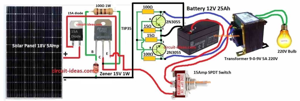
At first, when we switch to solar mode, the solar panel connects to the battery through emitter follower, and the battery starts charging.
When switch changes to inverter mode then solar panel disconnects and now battery connect to inverter.
Also, inverter uses transformer and flip-flop transistors to change battery DC to AC and then transformer makes AC voltage bigger and we get AC power at output.
Formulas:
Below are some easy formulas for emitter follower circuit and these help to set transistor bias and check AC working.
DC Biasing:
Base Current (IB):
IB depends on transistor gain (β) and how we connect the circuit and the formula for this is:
IB = (VCC – VBE) / RBias
where:
- VCC is the power supply voltage
- VBE is the base to emitter voltage which is around 0.6V for silicon transistor
- RBias resistor connected to base from voltage like in voltage divider
Emitter Current (IE):
Transistor gain tell how base and emitter current are link.
Formula:
IE = (β + 1) × IB
here,
- β or hFE is transistor gain.
AC Characteristics:
Voltage Gain (Av):
Voltage gain in emitter follower is almost 1 and it can be from 0.8 to 0.999.
Av = 1 (approx)
Note:
Also, these formulas give basic idea only and for more detail we can use small signal model.
How to Build:
To building a Solar Inverter Circuit with Charger follow the below mentioned steps for connections:
Solar Charger Connection:
- First, connect solar panel positive wire to TIP35 base.
- Next, connect solar panel negative wire to ground.
- After that, connect TIP35 emitter to battery positive (+).
- Then connect TIP35 collector back to solar panel positive.
- Also, a 15V Zener diode connects to TIP35 base and other end of Zener connects to ground.
- Then emitter follower output (+) connects to battery positive (+).
- After that, emitter follower output (–) connects to battery negative (–).
- Next, connect emitter follower output (+) also to one pole of SPDT switch and other pole of SPDT switch connects to solar panel positive.
- Also, common terminal of SPDT switch connect to battery positive.
Inverter Circuit Connection:
- First, use two 2N3055 transistors in cross-coupled way.
- Next, transistors collector connect to second transistors base and second collector to first base.
- Both emitters connects to battery negative (–).
- After that, primary winding of transformer connects to collectors of 2N3055.
- Then secondary winding of transformer connects to load like fan, light, etc.
- Also, SPDT switch common terminal connect to where collectors and transformer join.
- Then one SPDT pole connect to battery negative (–) and other pole connects to transformer negative end.
Testing:
Solar Charging Test:
- Put SPDT switch in solar charging mode and be sure battery is charging and voltage is not too high.
Inverter Test:
- First, put switch in inverter mode and check AC output from transformer secondary.
Important Notes:
- Be careful and always follow safety steps and do not let battery overcharge.
- Always make sure components handle the required power and add a fuse and check heat for safe use.
- Keep wires and parts tight and clean to avoid short circuit.
Safety Tips:
- Use fuse to stop too much current and use cut-off circuit to stop overcharging battery.
- Also, check temperature of transistor and transformer to stop overheating and be sure all wires are tight with no loose or wrong connection.
Conclusion:
Overall, this Solar Inverter Circuit with Charger is just a simple guide, but actual circuit may look different depending on parts we use and their power and voltage ratings.
Hence, always check datasheet of each part to know correct values and limits and if we do not know electronics well then better to ask help from someone who know or talk to a professional.
Also, follow local safety rules and electrical laws to stay safe.
Leave a Reply