Jet Engine Sound Generator Circuit using IC HT2844P is fun learning project and it makes jet engine sound using simple parts.
Furthermore, it uses IC HT2844P sound chip to make real jet noise which is good for model fans, school work or DIY fun; also circuit needs 3V power and keeps under 3.3V or else circuit may break.
Circuit Working:
Parts List:
| Components | Values | Quantity |
|---|---|---|
| Resistors (All resistors are 1/4 watt unless specified) | 220Ω | 1 |
| 470Ω | 1 | |
| 330k | 1 | |
| Preset 220k | 1 | |
| Capacitors | Electrolytic Capacitor 1µF 25V | 1 |
| Semiconductors | IC HT2844P | 1 |
| Transistor 2N2222 | 1 | |
| LED Any 5mm 20mA | 1 | |
| Speaker 8Ω 200mW | 1 | |
| Push Buttons | 4 | |
| Battery 3V | 1 |
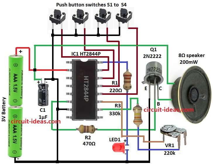
First, this circuit uses HT2844P chip to make jet engine sound, it runs on 3V from 2 AA batteries.
Then VR1 and R3 control sound pitch and speed and when ON chip makes jet sound from 8 ohm speaker.
After that, pins 12, 13, 14, 15 give different sounds when pressed to ground and then Q1 transistor makes sound louder for speaker.
Finally, R1 and R2 resistors keep parts safe by controlling current.
Formulas with Calculations:
Below are the formulas with calculations for Simple Jet Engine Sound Generator Circuit using IC HT2844P:
Current through R2 (I_R2):
I_R2 = (V_CC – V_BE) / R2
= (3V – 0.7V) / 470Ω
= 4.9mA
Power in R2 (P_R2):
P_R2 = I_R2² × R2
= (4.9mA)² × 470Ω
= 11.3mW
How to Build:
To build a Jet Engine Sound Generator Circuit using IC HT2844P follow below steps for connections and assembling:
- First, collect all parts from circuit diagram.
- Next, connect pin 2 of IC1 HT2844P to +3V battery and then put capacitor C1 across power lines of supply rails.
- Then one side of 8Ω speaker goes to + side of C1 and other side go to collector of Q1.
- After that, pin 6 of IC1 goes to base of Q1 through R2 and emitter of Q1 goes to GND and also pin 7 of IC1 connect to GND.
- Now pin 10 of IC1 goes to VR1 through R3 and other side of VR1 go to pin 11.
- Also, pins 12, 13, 14, 15 go to push buttons S1 to S4 and other side of buttons to GND.
- Further, pin 16 of IC1 goes to GND through R1 and LED1.
- Finally, +3V from battery goes to pin 2 of IC1 and negative side go to GND.
Conclusion:
To conclude, this Jet Engine Sound Generator Circuit using IC HT2844P is fun and simple project and it shows how sound chip and transistor work to make cool jet engine noise.
Leave a Reply